Home
Compact Two-Channel Amplifier for Stereo Systems (Audio August 1958)
- Details
- Category: Audio USA
- Hits: 241
Compact Two-Channel Amplifier for Stereo Systems
C.G. McPROUD
Audio August 1958
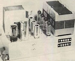
A simple and easily constructed stereo amplifier with plenty of power for all but the most elaborate stereo systems. Two pair of EL84's provide a clean 15 watts in each channel.
It is fairly well established that a single-channel amplifier for a high-quality monophonic system should have upward of 20 watts for good performance without the possibility of "breaking up" on peak signals. However, when two channels are employed in a stereo system it seems quite likely that the minimum for each is somewhere around 10 watts. One of the possible drawbacks to a stereo system is the increase in space demanded for actually housing the amplifiers - to say nothing of the speakers themselves - so it was felt that an amplifier could be designed that was adequate for most users, small in size, and big in performance. The amplifier to be described seems to fulfil these requirements very well.
Tube Selection
Selection of tubes in the 10- to 20-watt range is limited - if one wishes to keep size and power requirements to a minimum. The 6V6 would be adequate from the standpoint of power output, but this tube is notoriously poor from the standpoint of distortion.
Read more: Compact Two-Channel Amplifier for Stereo Systems (Audio August 1958)
More About Hum (Audio January 1957)
- Details
- Category: Audio USA
- Hits: 736
More About Hum
HAROLD REED
Audio January, 1957
After all of the obvious and usual means have been tried in an effort to eliminate a particularly troublesome case of hum, it may sometimes be found to be due to an unusual cause such as this.
MUCH HAS BEEN WRITTEN about hum in audio amplifiers. The author has somethimes thought, in some of his writings, that he had covered the subject quite thoroughly, onle later to be encountered by hum conditions in circuitry not presented before by the writer, nor found discussed in other articles. One such condition will be considered in this article.
It is well known to audio amplifier constructors, that the input tube operating with low signal levels - such as the first tube in a preamplifier - should have minimum heater heater to cathode leakage. This leakage is due to a current flow between heater and cathode, which elements are separeted by a special type of insulation.
There are numerous ways to ease or eliminate objectionable hum in the amplifier output due to this leakage. As they have been well covered in technical publications, they will not be enumerated here. One of the most effective, of course, is to place the cathode as near to ground potential as possible. A large cathode bypass capacitor is normally used for this purpose.
A Quality Dynamic Headphone Tube Amplifier
- Details
- Category: Glass Audio
- Hits: 313
A Quality Dynamic Headphone Tube Amplifier
by Helmut Becker and Michael Oberesch
Glass Audio 01-0-1988
Only a few of us are privileged to listen to music at a volume comparable to the original performance. It's not because we lack appropriate equipment, but rather the neighbors force us to reduce the volume. There are two answers to this problem. We can either move to an apartment far away from civilization, or we can use headphones. The second option is definitely less expensive and offers an additional advantage: for quality sound, no loudspeaker can compete with headphones.
Most stereo manufacturers seem to ignore the fact that headphones are among the best transducers. Nearly all amplifiers have a headphone jack, but this output is often inadequate at best.
Plain, Bad, Simple
Usually, headphones are connected in parallel with the loudspeakers, where, as an option, the loudspeakers may be switched off. Headphone systems are available with impedance from 8 to 2kΩ, but usually a resistor with approximately 300Ω is connected in series with the headphones.
This prevents overloading from too high a voltage at the 8Ω loudspeaker output. When connected to high impedance systems, this resistor causes only a negligible voltage drop.
Speaker array - design
- Details
- Category: Educational tools
- Hits: 311
Directional line source
Prepared on the basis of the results of research task No. II-41 carried out in 2021-2023 entitled "Research on acoustic field control on the example of a matrix sound source with controlled directional characteristics" financed by the Ministry of Education and Science from a subsidy for the maintenance and development of teaching and research potential.
The directional line source was developed according to the dimensions shown in Fig. 1. The source is 380 mm wide, 100 mm high and 65 mm deep. The 60 mm wide loudspeakers are arranged in such a way that a distance of 20 mm separates them from the edge of the source, and a free space of 10 mm is left between the loudspeakers. When designing the housing, the rule was to make it as narrow as possible to avoid spatial aliasing.
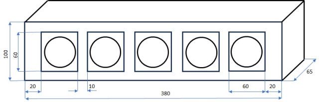
Fig. 1 Geometric dimensions of a linear directional source
The directional line source uses FR58-8 (8Ω) loudspeakers from Visaton. The view of the loudspeaker from the side of the diaphragm and the magnet is shown in Fig. 2. The loudspeaker is mounted with four screws. The coil terminals are located on the magnet side.
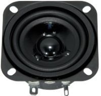
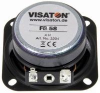
Fig. 2 View of the loudspeaker used in the directional source
The geometric parameters of the loudspeaker are shown in Fig. 3.
Speaker array - measurements
- Details
- Category: Educational tools
- Hits: 286
Speaker array - measurements
Prepared on the basis of the results of research task No. II-41 carried out in 2021-2023 entitled "Research on acoustic field control on the example of a matrix sound source with controlled directional characteristics" financed by the Ministry of Education and Science from a subsidy for the maintenance and development of teaching and research potential.
The possibilities of controlling the distribution of the sound field are closely related to the directivity characteristics of sound sources. Sources with high directivity allow for appropriate determination of the sound field distribution. This distribution is consistent with the directivity characteristics of the source in the free field and differs from the directivity characteristics of the source, the more the area in which the source is located is similar to the reverberant field. In other words, in an anechoic chamber or open space, the distribution of the sound field is consistent with the directionality characteristics of the sound source, while in a reverberation chamber, the directionality characteristics do not affect the sound field distribution. Of course, the mentioned compliance concerns the relative difference in the sound pressure level for a specific distance from the sound source, because the sound pressure level decreases with the distance from the source.
The reasons presented above were the reason for using directional sound sources to provide specific amplification of large mass events taking place in open spaces or rooms with large volume (dimensions) and a high absorption coefficient of the surfaces limiting the interior.
6ZAF Furnishes Astronomical Time by Radio (Radio 11/1921)
- Details
- Category: Radio USA
- Hits: 665
6ZAF Furnishes Astronomical Time by Radio
RADIO for November, 1921
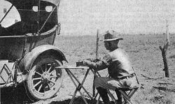
For the first time radio has successfully furnished the official time for an important astronomical expedition. But in the words of Director W. W. Cambell of the Lick Observatory and head of the party that went into the desert wilds of Lower California to select observing stations for the eclipse of the sun. September 10, 1923, "it will not be the last time". An interesting story is involved in the part played by radio in this expedition and by 6ZAF, who in public life is A. H. Babcock, electrical engoneer for the Southern Pacific Railroad and an enthusiastic radio fan.
Late in the morning of the day on which this scientific expedition was to leave San Francisco, Director Campbell telephoned to Mr. Babcock that the chronometer on which they were to depend in making their observations of latitude and longitude had been broken and could not be replaced at the last minute. Whereupon 6ZAF said that if he could get together a receiving set and one of those devices that have made the dollar famous no chronometer would be needed. The time signals from San Diego would be more accurate than any single chronometer and could easily be picked up 200 miles away.
Read more: 6ZAF Furnishes Astronomical Time by Radio (Radio 11/1921)
Output Transformers - Part I and II (Audio 1960/02/03)
- Details
- Category: Audio USA
- Hits: 1009
Output transformers - Part I and II
An easy-to-understand discussion of the factors that affect the performance of all output transformers.
Author: JAMES MOIR (Technical Director, Goodmans Industries, Ltd., Wembley, Middx., England).
AUDIO, FEBRUARY-MARCH, 1960, VOL. 44, No. 2-3 (Successor to RADIO, Est. 1917).
The output tubes in common use in audio amplifiers require anode loads of between about 1000 ohms and 10000 ohms if the maximum undistorted power output is to be obtained. There are practical difficulties in winding a loudspeaker voice coil with the large number of turns of fine wire required to achieve such high load impedances directly and thus it is common practice to insert an output transformer between a speaker of low impedance and the output valves as in Fig. 1 in order to "match" the speaker to the valves. The ensuing discussion is intended to be a simple explanation of this matching process and of all the factors that control the frequency response and the distortion introduced by an output transformer.
Fig. 1. Output transformer used to obtain the correct load impedance and isolate the voice -coil current from the plate supply.
Loudspeaker voice coils can be wound with sufficient turns to give an impedance of 3 ohms to 4000 ohms and, in fact, these were common in the very early days of radio.
Read more: Output Transformers - Part I and II (Audio 1960/02/03)
Wzmacniacz sieciowy (Mains powered amplifier) "5L"
- Details
- Category: Radioamator
- Hits: 908
Mains powered amplifier "5L"
Radioamator, Year III, February 53, No 2
MSc. Czeslaw Klimczewski
In the previous issue of our magazine, a description of the installation of the loudspeaker pickup working in the "push-pull" system was given. The so-called "phase reversal" was obtained in this pickup by means of a vacuum tube, not a transformer. Thanks to not using a transformer and a low-frequency choke, the cost of the amplifying attachment is relatively small and the difficulties in its assembly are also not very high..
Now, developing the scheme of the amplification box, a full 25 watt amplifier will be described, which has a wide range of applications.
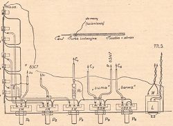
As we can see from the schematic diagram shown in Fig. 1 - this amplifier is adapted to be powered with alternating current from the mains with different voltages (from 220 V to 110 V). The first two tubes from the "input" side to the amplifier, i.e. the 6SC7 and 6AC7 tubes - play the role of the so-called "preamplifier", in which the voltages received from microphones, adapter or receiver obtain the appropriate height in order to properly drive the final stage, consisting of a 6SN7 tube reversing the "phase|" and amplification, and two 6L6 tubes operating in push-pull arrangement, providing the necessary power to power the loudspeakers.
Read more: Wzmacniacz sieciowy (Mains powered amplifier) "5L"
The Vacuum Tube as an Amplifier (Radio 7/1922)
- Details
- Category: Radio USA
- Hits: 1076
The Vacuum Tube as an Amplifier
By B.F. McNamee
Radio for July, 1922
The type of vacuum tube used as an amplifier is the "hard" or high vacuum tube. The vacuum is so nearly perfect that there is no noticeable effect of gas molecules; in fact for practical purposes it may be considered a perfect vacuum. The "soft' tube, that is one containing a certain small pressure of gas and intended for use as a detector, can be used to a certain extent for amplification purposes. However this almost always results in distortion which would prohibit its use as an amplifier in radio telephone work, and its use is also restriced because it will not work with high plate voltage, thus limiting the strength of signals that can be obtained.
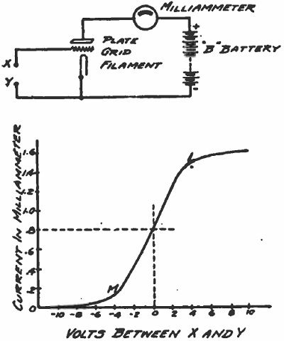
Fig. 1 and Fig. 2
The hard tube therefore is the only one that will be considered in this article.
Device for testing electron tubes - Przyrząd do badania lamp (Radio dla Techników i Amatorów 1949/10)
- Details
- Category: Radio dla Techników i Amatorów
- Hits: 2314
Device for testing electron tubes
(Radio dla techników i Amatorów, Październik 1949, Rok IV, Nr 10)
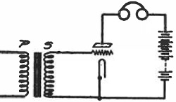
In our monthly magazine, we have not yet described an important and basic instrument, which is the practice of a radio amateur and radio technician - a device for testing electric lamps. Twice, however, such a device was described by our brotherly weekly "Radio i Świat", namely in 1945 No. 15 entitled "Instrument for testing the emission of electron tubes" and in 1947 No. 36/37 entitled "Instrument for testing electron tubes". Both of these apparatuses made use of the same principle, shown in Fig.1. The mains transformer has a secondary winding of the filament of the vacuum tube and some additional winding giving an effective voltage of up to 20 volts. The end of this winding is connected, through a limiting resistance of 500 ohms, protecting against the effects of possible short circuits or overloads, and a DC milliammeter - to the anode and other high-voltage electrodes of the tested electron tube. Other electrodes, such as the control grid, are shorted to the cathode, which in turn has a common point with one glow pole. When a vacuum tube is inserted into a suitable socket, a one-way current will flow through it after heating up and cause the milliammeter to deflect. The above mentioned descriptions are accompanied by tables of "normal" deflections of more electron tubes.
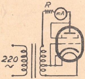
Fig. 1. Principle of operation of the most primitive device for testing electron tubes. All electrodes are connected either to the anode or to the cathode. A one-way rectification system is obtained, and the device measures the rectified current, which depends to some extent on the emissivity of the cathode. The shortcomings of this instrument are discussed in the text.
Instruments of the type shown in Fig. 1 operate on the principle of one-way rectification. Each electron tube, regardless of its proper purpose, is of course capable of rectifying, and it does so in a manner dependent to some extent on its "emission". Of course, there is no need to emphasize that the system in which we examine vacuum tubes is not even roughly similar to the conditions in which the vacuum tubes we use work in amplifiers, receivers, oscillators, etc. It even happens that we do not see a case at all any vacuum tube was ever supposed to work under such or even similar conditions.
Page 1 of 10
Select your language
")
")
")
")
")