Universal Feedback Amplifier Circuit
ARNOLD J. KAUDER (Principal Engineer, Bendix Aviation Corporation, North Hollywood, California)
AUDIO, January, 1960, VOL. 44, No. 1
A simple amplifier of exceptional performance which should be adequate for practically any installation is the basis for this article, but its greatest value lies in the "universal" instructions for adjusting any feedback amplifier.
(Note: The original notation of units used at the time of writing the article has been preserved.)
The amplifier to be described has performed well with five different output transformers, which has led the writer to use the designation "universal." The amplifier has in each case been found completely stable with (a) no load, (b) 8-ohm resistive load, (c) 8-ohm loudspeaker load, and (d) a 0.1 μF capacitor load added to any of the load conditions of (a), (b), or (c) above. The feedback factor employed has been 20 db ± 1 db.
Few of the "Williamson Type" and other amplifiers seen by the author have been capable of meeting such a stability test. Breathing of the loudspeaker cone, due to very-low-frequency oscillations, and supersonic oscillations readily seen on an oscilloscope are all too common. Either type of oscillation can produce negative charges on the grid sides of the output-tube coupling capacitors, with distortion and limited power output resulting. Marginally stable amplifiers have also been observed which do not normally oscillate, but are highly regenerative at extreme frequencies and do oscillate when audio signals with steep leading edges on the waveforms are fed to the input terminals.
A brief history of the development of the circuit is believed to be of interest and is as follows:
Development
The author was a "high fidelity" fan many years ago and is still not ashamed of the performance of a class-A push-pull 2A3 triode amplifier (power output of 7 watts) still on hand. After a lapse of 10 years, a reviewed interest in high fidelity led to a study of feedback and the present day amplifiers which have achieved recognition in the literature. The writer found to his annoyonce that it was not possible to duplicate a published amplifier circuit and employ a different output transformer and a more compact layout - unless extensive redesign of the coupling and feedback circuits was carried out.
The author then made an analysis of the problems in the design of feedback amplifiers and established the following principles for his own amplifier.
- It should have as few stages as possible to achieve the required gain. Extra stages contribute phase shifts at low and high frequencies which reduce the inherent stability of the amplifier.
- The simplest possible circuitry should be employed. Additional components which are not necessary simply add to the cost, complication, and potential for failure.
- The output stage should be biased for Class A operation. It is not generally realized that plate current cutoff in a power output tube biased to AB operation can cause ringing and oscillation, as well as other forms of distortion due to the steep wavefronts in the output transformer current waveform.
- Multiple feedback paths should be employed, rather than a single path from output to the input, to achieve maximum stability.
- Although the author is of the school which believes that a power output of 6 watts is adequate for the home, a power output between 15 and 20 watts should be employed to assure near-perfect linearity at the normal maximum 5 -watt home listening level and to allow a reserve margin of power to compensate for tube aging, inefficient or mismatched speakers and other variables.
Circuitry
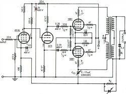
The schematic of the resulting amplifier is shown in Fig. 1, and its power supply in Fig. 2. It consists of a pentode voltage amplifier directly coupled to a split-load triode phase splitter, which is resistance coupled to the push-pull output pentodes. Actually, the amplifier may be thought of as the simplest two-stage pentode resistance-coupled type, with the phase splitter added to convert the design to push-pull operation. This simple straightforward design is neither startlingly new or even original, but fulfills admirably the requirement of the least possible number of stages and coupling networks. This is the initial key to stability in a feedback amplifier. The final key to the high level of stability lies in the three feedback paths, which will be discussed in a later paragraph.
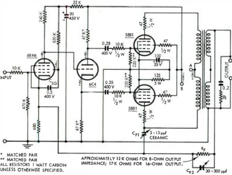
Fig. 1. Schematic of the author's "Universal" feedback amplifier.
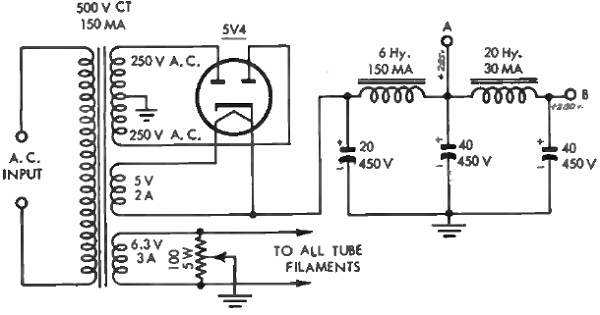
Fig. 2. Power supply for the "Universal" amplifier.
To satisfy the Class A and power design requirements, the output tubes had to be beam power tubes of the 6L6 type, with improved construction as exemplified in the type 5881 and 6L6GB. No available triodes are capable of providing either the high gain, or the power output in Class A operation which beam power tubes provide - and provide with modest power supply and driver stage requirements. Stabilizing resistors of suitable values are employed in the grid, screen grid, and plate circuits. The tubes are self-biased, since fixed bias does not appear to offer any advantage with beam-power tubes, while self bias permits the use of higher impedance in the grid circuits, with less loading of the driver stage.
The push-pull output stage is driven by a split-load or eathodyne phase splitter employing a type 6C4 miniature triode. After considerable study of phase splitters, this type is considered by the writer to be superior to all others, including the cathode-coupled inverter - actually the only other type deemed worthy of consideration. There has been much talk about unbalance of the cathodyne phase inverter at high frequencies, but after reference to the available literature, the author considers this to be much talk not based on adequate investigation.
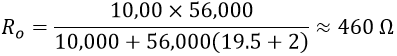
Actually, the equivalent source impedance of either output channel is1:
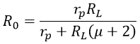 |
(1) |
Substituting a value of 56,000 ohms for RL, 10,000 ohms for rp and 19.5 for it as applicable for the 6C4 tube employed in this amplifier,
The output capacitances Co for each channel are, respectively1:
Plate Channel:
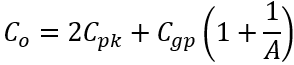 |
(2) |
Cathode channel:
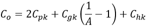 |
(3) |
where:
- A - the channel gain of approximately 0.9
- Cpk - plate-to-cathode tube capacitance
- Cgp - grid-to-plate tube capacitance
- Cgk - grid-to-cathode tube capacitance
- Chk = heater-to-cathode tube capacitance
For a 6C4 triode:
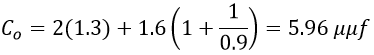
- Cpk = 1.3 μμF
- Cgp = 1.6 μμF
- Cgk = 1.8 μμF
- Chk = 2.5 μμF
Substituting these values in Eqs. (2) and (3):
Plate channel:
Cathode channel:
If these output capacitances are added to values of 10 μμf for wiring and 10 μμf for the input capacitance of the power output tubes, the total shunting capacitance of the two channels are 25.96 μμf and 25.28 μμf respectively, a difference of 0.68 μμf or approximately 1.5 per cent. Referring back to Eq. (1), the value of 460 ohms equivalent source impedance Ro with a shunting capacitance of 30 μμf will result in an output within 3 db of mid-frequency output beyond 10 mc, well outside the range of any audio amplifier this citizen ever wishes to possess. Any unbalance within the range up to a few hundred kilocycles is considered negligible.
As employed, the cathodyne splitter contributes little phase shift, is virtually free of distortion itself, is easily balanced with two matched load resistors and readily meets the driving requirements of 30 volts peak-to-peak output for the two power output tubes. The phase splitter is direct coupled to the input amplifier tube, a high transconrluctanee type 6BH6 miniature pentode. The design of the first stage is conventional. However, the screen grid potential is chosen to permit operation with a relatively low value of bias resistor in the tube cathode circuit, to reduce the impedance of the main feedback network.
While it is believed that other triode and pentode tubes of similar characteristics may be employed in the first two stages, the 6BH6 and 6C4 were chosen because they have low heater currents (150 ma), which have been found to minimize hum problems.
Reasons for Stability
The high degree of stability in this amplifier is achieved by means of three negative feedback paths of the simplest type as described below :
- The first stage has an unbypassed cathode resistor, which constitutes the first path providing negative feedback.
- A small adjustable capacitor Cf1, (3-12 μμF) connected between the plate of one output tube and the cathode of the input amplifier tube, provides the second negative feedback path. This path provides considerable feedback at the supersonic frequencies, eliminating the peak found in this region as the feedback factor is increased.
- The third feedback path is provided by a voltage divider connected across the output transformer, consisting of the feedback resistor Rf and the 680-ohm unbypassed cathode resistor of the input pentode amplifier tube.
An adjustable capacitor Cf2 = (30 - 300 μμf) is connected across the feedback resistor to provide control of the feedback factor at the higher frequencies below the peak leveled by Cf1, discussed above.
Adjustment Procedure
The following procedure should be employed to adjust the feedback networks for stable operation of the Universal Amplifier.
- With Cf1, Cf2. and the main feedback resistor Rf, disconnected, run a response curve on the amplifier with a 4 , 8-, or 16-ohm resistor connected to the proper amplifier output terminals. Depending on the quality of the output transformer, the response should be level within about 3 db (30 per cent approximately) of the midrange response (400 to 1000 cps) to about 10,000 cps or higher. Any reasonable audio oscillator covering from 20 to 100,000 cps is suitable.
- Connect a 25,000-ohm variable resistor to maximum resistance as Rf and note whether the amplifier gain decreases. If it increases, reverse the output tube plate connections to the output transformer, or reverse the connections tc the secondary winding of the output transformer.
- Decrease the value of Rf slowly and look for a peak in the response of the amplifier in the high frequency ranges (usually found at about 40,000 cps or higher).
- Connect Cf1, and adjust as required to eliminate the high-frequency peak discussed above.
- Continue to decrease Rf and readjust Cf2, as required until the amplifier gain is reduced to one tenth of the value without feedback. This is a feedback factor of 20 db. With all but the highest quality output transformers a second response peak, in the frequency range somewhere between 17 and 30 kc will usually become evident. This peak will be considerably broader than the first response peak.
- Connect Cf2 and adjust as required to level the second peak.
- Check the amplifier frequency response again and make slight readjustments of Cf1, and Cf2, as required to level any rises in the response curve. Connect the loudspeaker in place of the load resistor and repeat this step.
- The amplifier may now be given the acid test of connecting capacitors across the output terminals. If the amplifier is not stable with at least a 0.02 μf capacitor across the output terminals further adjustments of Cf1, and Cf2 should be made as necessary. Rf and Cf2 should now be measured and replaced with fixed value components.
If a peak in the low-frequency response of the amplifier becomes evident during the feedback adjustments, the value of the screen-to-cathode bypass capacitor Csg of the input pentode amplifier may he reduced (in one case from 0.5 μf to 0.05 μf) to level the low-frequency response.
Feedback factors as high as 40 db (a reduction of 100:1 in gain) have been achieved with high-quality transformers. However, the amplifier then requires a 10-volt rms input signal for 15 watts output, whereas approximately one volt is sufficient for full output with 20 db of feedback. No difference in listening performance has been discernible with increase of the feedback factor beyond 20 db.
If any perfectionist (more power to such) does not accept the balance of the cathodyne phase splitter as being adequate, he may achieve theoretically perfect balance by adding a small adjustable capacitor across the cathode load resistor and check for perfect balance in the megacycle region. However, no test instruments should be connected to the cathodyne inverter itself, or the inherent added capacitance will invalidate the test results. The balance measurements must be made at the plate terminals of subsequent stages.
The author has tried the "ultra-linear" connection of the output tubes but has observed no advantage in performance to compensate for the reduction in gain. Those who prefer this method of output tube operation may change the bias resistor to a value approximating that for triode operation of the output tubes and follow otherwise the procedure outlined in this article.
This amplifier has been termed "Universal" since it is believed capable of producing the optimum performance which is obtainable from any output transformer of suitable impedance ratios. There is no reason to believe that larger and smaller power tubes than the type 5881 cannot be used with equal success. However, the author takes a dim view of any type of operation of the output tubes except class A unless the output transformer is a top-grade unit and the screen grids of the output tubes are fed from a regulated power supply.
Additional Suggestions
The following notes are offered to prospective builders of the Universal Amplifier.
- Note 1: The network across the transformer output terminals is intended to provide increased stability at high frequencies with no load. It is not needed with the best output transformers.
- Note 2: It is recommended that all grounded leads be made to a common buss bar, which is isolated from the chassis except at the ground terminal of the input connector.
- Note 3: No bias balancing control for the output tubes has been employed, since the 6L6GB and 5881 tubes seem to be quite uniform.
- Note 4: The center tap of the 100-ohm balance potentiometer connected across the heater winding is grounded, since this connection makes hum inaudible with the ear at one foot from the loudspeaker. With different tubes or a different layout, it may be advisable to return the potentiometer center tap to a positive potential, which may be provided by a resistive voltage divider at the output of the power supply. Positive potentials up to about 55 volts may be investigated for minimum hum.
- Note 5: The author's speaker system calls for an 8-ohm output impedance and this was provided on each output transformer
used. Values of 16 or 4 ohms will require a different value of feedback resistor Rf. The primary impedance should be between 5000 and 7000 ohms for type 5881 and similar tubes.
Distortion and intermodulation measurements have been made, but will not be presented in this article. Suffice that the amplifier is essentially distortionless up to the overload point of the output tubes or transformer, whichever is reached first. The frequency response is flat from the low-frequency limit of the output transformer to somewhat higher than the resonant frequency of the output transformer, beyond which the response falls smoothly at a rate of 6 to 10 db per octave. The resonant frequencies of the transformers used have ranged from approximately 38 to 100 kc.
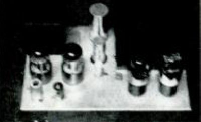
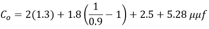
Fig. 3. Top view of the amplifier described.
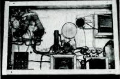
Fig. 4. Bottom view of the author's amplifier.
Figures 3 and 4 are top and bottom views of one version of the Universal Amplifier which provides plate and filament power for a large AM -FM radio phonograph console, and therefore uses two 5V4G rectifier tubes.
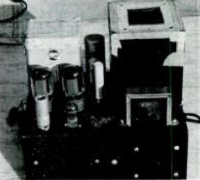
Fig. 5. Another embodiment of the "Universal" amplifier - this one uses silicon rectifiers in the power supply section.
Fig. 5 is view of a second version of the Universal Amplifier using silicon rectifiers in the power supply. Masking tape used to protect the paint finish of the transformers during construction is shown in Fig. 5 as a useful suggestion.
1 "Radiotron Designer's Handbook", Edited by H. Langford-Smith, Fourth Edidion, p. 330.