
Stereo amplifier
Młody Technik 1972/09 (Young Technician 1972/09)
MSc. Franciszek Lesiak
The amateur construction of a high-quality stereo amplifier is very difficult and requires a lot of theoretical knowledge, practical skills, as well as considerable financial resources. Therefore, we offer those who are interested in making a simplified high-quality amplifier, not necessarily HI-FI, but with better parameters than the amplifiers described so far in the "Young Technician" magazine.
The device is characterized by a significant output power sufficient to amplify a large room, e.g. a common room, club, etc., a wide band of transmitted frequencies and a low coefficient of non-linear distortions.
The audio set consists of an amplifier and two loudspeakers. Basic data of the amplifier:
- 2 x 10 W output power with a distortion of 1.5%,
- Frequency response 30 ÷ 15,000 Hz,
- Sensitivity 0.2V,
- Tone adjustment:
- ± 10 dB at 50 Hz,
- ± 10 dB at 10 kHz,
- Dimensions 440 × 230 × 110 mm.
The schematic diagram of the amplifier is shown in Fig. 1. Each channel of the system contains a three-stage power amplifier in a push-pull circuit built on EL84 tubes, and also a gain and tone control system.
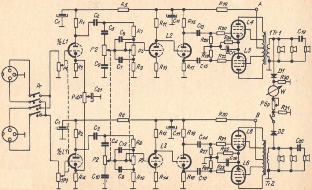
Fig. 1. Schematic diagram of the amplifier
The input signal from one of the two input sockets goes through a switch Pr to the potentiometer P1 used to adjust the volume, and then to the grid of the tube L1, which is the first stage of voltage amplification. Both cathodes of the tube L1 are connected to the leads of the potentiometer P4, the slider of which connects to the capacitor C21.
Changing the position of the potentiometer slider reduces the negative feedback on resistors R3 or R4, and thus changes the gain of individual channels. This is called balance regulator. Due to the fact that the P1 potentiometer has no DC voltage, this system does not cause unfavorable noises during the adjustment.
From the anode resistor R1, the acoustic signal flows through the capacitor C2 to the tone corrector. The equalizer system allows not only to attenuate high and low acoustic frequencies, but also to amplify them, thanks to which the frequency characteristics of the received signal can be shaped within wide limits. In the upper position of the slider of the potentiometer P2, the treble is raised when the resistor R7 is bypassed by the capacitor C5. In the low position, the treble is cut off. The P3 potentiometer is used to adjust the bass and works similarly.
The signals from both potentiometers are collected and enter the grid of the first half of the L2 tube, which is the second stage of voltage amplification. The anode of this tube is connected directly to the grid of the other half of the L2 tube. Such a system increases the transmitted bandwidth towards lower frequencies and reduces the phase distortions caused by the amplifier.
In order to make such a connection possible, the anode resistance R11 is relatively large so that the grid of the second half of the tube L2 receives the negative voltage necessary for the correct operation of the amplifier. The other half of the tube L2 is a phase inverter and causes a polarity-dependent signal to be applied to the grid of the tube L4 or L5. R20 and R22 resistors prevent the amplifier from excitation.
The anodes of the L4 and L5 tubes are connected to the midpoint of the output transformer. The shielding grids of these electron tubes are connected to the taps on the transformer. This creates negative feedback in the circuit of the shielding grids, which significantly reduces the nonlinear distortion caused by the power amplifier. This is called "ultralinear" system.
To control the correct setting of the balance regulator, a microammeter was used, connected to the secondary windings of both transformers through diodes D1 and D2, and a potentiometer P5 with a switch, used to adjust the sensitivity of the device. The device's zero point should be placed in the middle of the scale.
The loudspeaker transformers were made on their own on the cores of the mains transformers used in the "Bolero" receivers. The data and location of the transformer windings are shown in Fig. 2. As a substitute, ready-made loudspeaker transformers from the "W 600" stereo amplifier or the "Dueton" audio set can be used, but then the output power will be slightly lower.
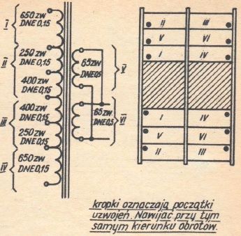
Fig. 2. Data of loudspeaker transformers
Both amplifier outputs are connected to the loudspeakers. In each loudspeaker there are two GD25 / 18-5 woofers (mid-range) connected in parallel and in phase and the GDW6.5-1.5 tweeter connected in aphase through a capacitor (C19, C20) to prevent low frequencies from reaching the loudspeaker.
The power supply of the amplifier is shown in Fig. 3. It consists of a mains transformer from the Soviet TV "Rubin 106" and selenium rectifier stacks Pr1, Pr2 and filtering capacitors CZ1, CZ2.
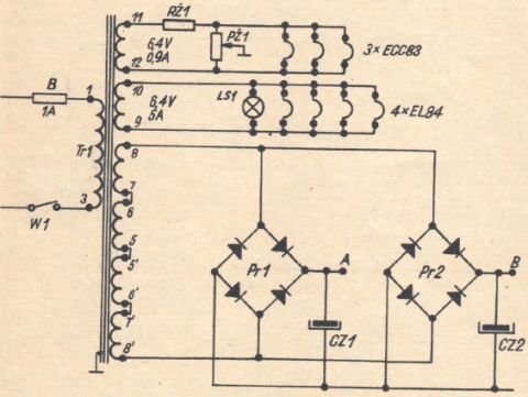
Fig. 3. Amplifier power supply
In order to reduce mains hum, in the filament circuits of the electron tubes of the voltage amplifier there is a resistor RŻ1, which reduces the filament voltage, and a potentiometer PŻ1, which is set at the minimum audible hum.
The mains transformer can be wound if we have a core with a cross-section of about 20 cm2. The primary winding has 526 turns wound with the DNE Ø 0.5 mm wire, the secondary winding - 710 turns wound with the DNE Ø 0.3 mm wire. The heating of ECC83 tubes should have 15 turns of DNE Ø 0.8 mm, and the winding of heating of EL84 tubes should have 16 turns of DNE Ø 1.2 mm.
The interior of the amplifier is shown in the photo. It consists of a front panel, a chassis and a rear panel, which are connected by means of distance bolts with a diameter of 12 mm, on one side provided with an M6 × 15 mm hole, and on the other side with an M6 × 10 mm thread.

The inside of the amplifier
The front and rear panels are made of 4 mm thick aluminum sheet, and the chassis is made of 1.5 mm thick steel. The entire metal structure is inserted into a wooden box covered with a laminate with veneer imitation. Holes should be made in the box at the top and bottom for cooling the elements of the amplifier.
The assembly diagram of the electric system is shown in fig. 4. During assembly, the rules applicable to the construction of this type of devices should be followed: the connection of the grids of the electron tubes should be made with a wire in the screen, the earthing bar connecting the electron tube sockets, made of wire with a diameter of at least 2 mm and connect with the chassis only in one point, lead the wires connecting the tubes filaments to the other side of the chassis.

Fig. 4. Assembly diagram of the amplifier
The housings of the loudspeakers (Fig. 5) are made of plywood 15 mm thick as closed housings. There are loudspeakers on the front wall of the loudspeaker housings.
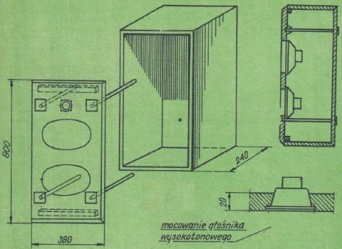
Fig. 5. Loudspeaker housing
The front and back of the column are connected with pullers with a 40 × 40 mm sheet on one side, and an M8 thread on the other. The front wall is covered with decorative canvas, and the side walls are covered with a laminate imitating a veneer in the same color as the amplifier housing.
List of components of the amplifier
- Resistors
- R1, R2 - 47kΩ/0,25W
- R3, R4 - 1kΩ/0,125W
- R5, R6 - 22kΩ/0,25W
- R7, R8 - 47kΩ/0,125W
- R9, R10 - 10kΩ/0,125W
- R11, R12 - 470kΩ/0,25W
- R13, R14 - 1,5kΩ/0,125W
- R15, R16, R17, R18 - 100kΩ/0,25W ±5%
- R19, R32 - 10kΩ/0,25W
- R20, R21, R22, R23 - 1kΩ/0,125W
- R24, R25 - 130kΩ/2W
- R26, R27, R28, R29 - 470kΩ/0,125W
- R30, R31 - 4,7kΩ/0,125W
- RŻ1 - 1Ω/2W
- Potentiometers
- PŻ1 - 100Ω/2W
- P1 - 2×1MΩ - C
- P2, P3 - 2×1MΩ - A
- P4 - 5kΩ - A
- P5 - 10kΩ - A
- Capacitors
- C1 - 2×50μF/450V
- C2, C3 - 0,047μF/250V
- C4, C5 - 220pF/250V
- C6, C12 - 3000pF/250V
- C7, C8 - 20000pF/250V
- C9, C10 - 3000pF/250V
- C11 - 2×50μF/450V
- C13, C14, C15, C16 - 0,047μF/250V
- C17, C18 - 100μF/25V
- CZ1, CZ2 - 2×50μF/450V
- Electron tubes
- ECC83 - 3 pcs.
- EL84 - 4 pcs.
- Selenium rectifier element SPS - 6B - 250 - 100 - C - 2 pcs.
- Loudspeakers
- GD 25 / 18 - 5W - 4 pcs.
- GDW 6,5 - 1,5 W - 2 pcs.
- Transformers as described in the text
- Microammeter from the "Sonet" tape recorder
- Sockets, sockets for electron tubes, lamp, fuse, mounting strip and other small assembly elements.
The content of the article for electron tube enthusiasts was provided by Grzegorz 'gsmok' Makarewicz.