Radio engineering time travel (1928)
I invite you to look at the "pictures" related to radio technology in 1928. They come from various sources. The gallery has its sister version in Polish and Russian. Versions in other languages will be added successively. More detailed descriptions can be found in other language versions (articles are related and can be displayed by clicking on the icons with flags on the left, top of the TRIODA website). Of course, I will complement translations of signatures quite slowly. All descriptions are displayed using the present tense and not the past - this is not a mistake only deliberate action - a reference to the original descriptions from those years. In order not to delay the possibility of viewing the gallery, this site is made available as a "site under construction" - for which I apologize to all guests. At the beginning and end of each set of photographs there are links allowing to change the period - calendar year.
[Previous period] [Next period]
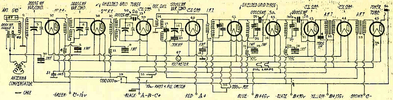
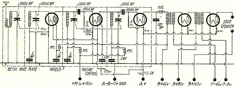
Schematic Wiring Diagram.
Article: The 115 Kilocycle Superheterodyne With Shielded Grid Tubes in Two Stages of R. F. and I. F. Amplification So As to Give Unequalled Sensitivity, Selectivity and Quietness.
(Radio for January, 1928)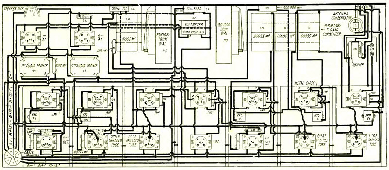
Pictorial Wiring Diagram, Showing Layout of Apparatus.
Article: The 115 Kilocycle Superheterodyne With Shielded Grid Tubes in Two Stages of R. F. and I. F. Amplification So As to Give Unequalled Sensitivity, Selectivity and Quietness.
(Radio for January, 1928)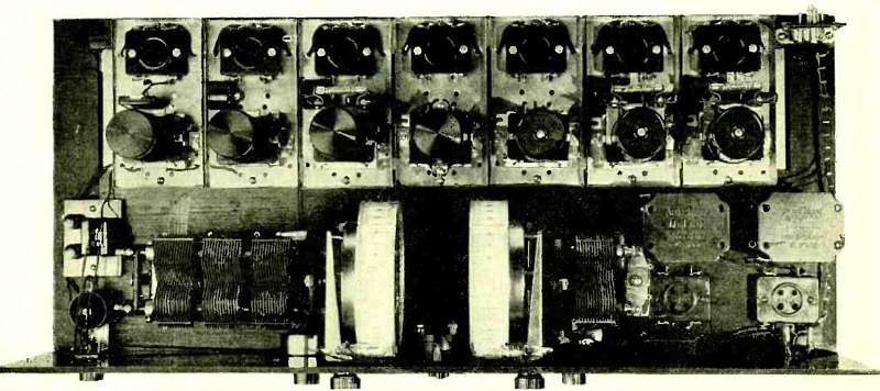
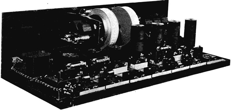
Top View of Superheterodyne.
Article: The 115 Kilocycle Superheterodyne With Shielded Grid Tubes in Two Stages of R. F. and I. F. Amplification So As to Give Unequalled Sensitivity, Selectivity and Quietness.
(Radio for January, 1928)
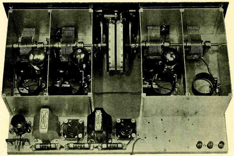
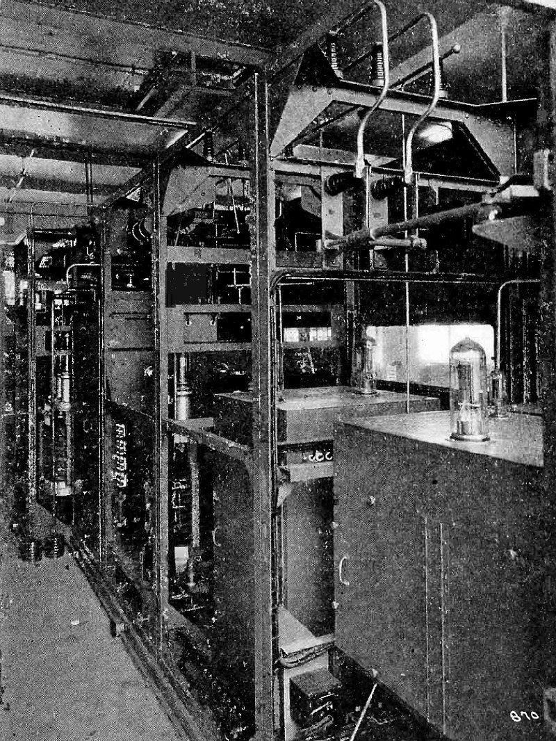
Rear View of Superheterodyne With Shield Units Removed.
Article: The 115 Kilocycle Superheterodyne With Shielded Grid Tubes in Two Stages of R. F. and I. F. Amplification So As to Give Unequalled Sensitivity, Selectivity and Quietness.
(Radio for January, 1928)
Circuit Diagram of 1928 "Hi -Q" Adapted for Shielded Grid Tubes.
Article: Shielded Grid Tubes in the 1928 "Hi_Q".
(Radio for January, 1928)
The 1928 "Hi -Q" with Shielded Grid Tubes.
Article: Shielded Grid Tubes in the 1928 "Hi_Q".
(Radio for January, 1928)
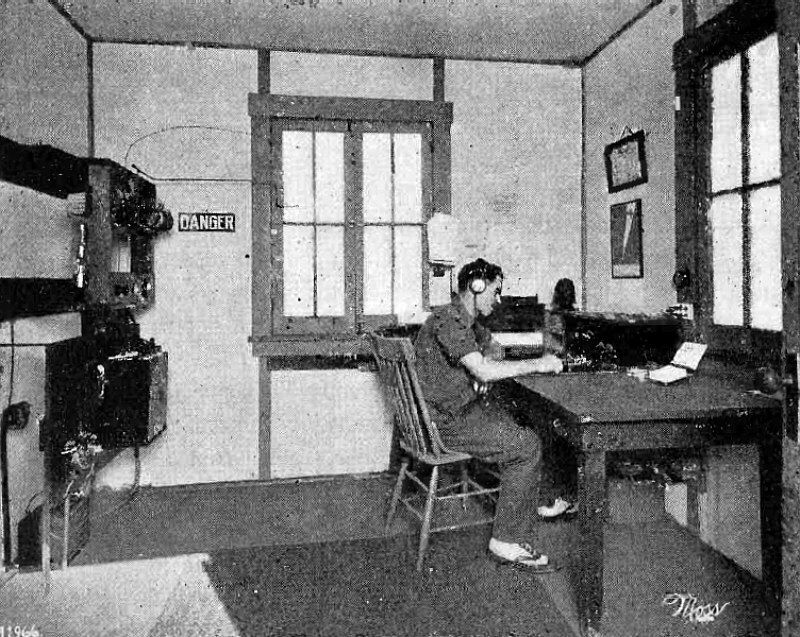
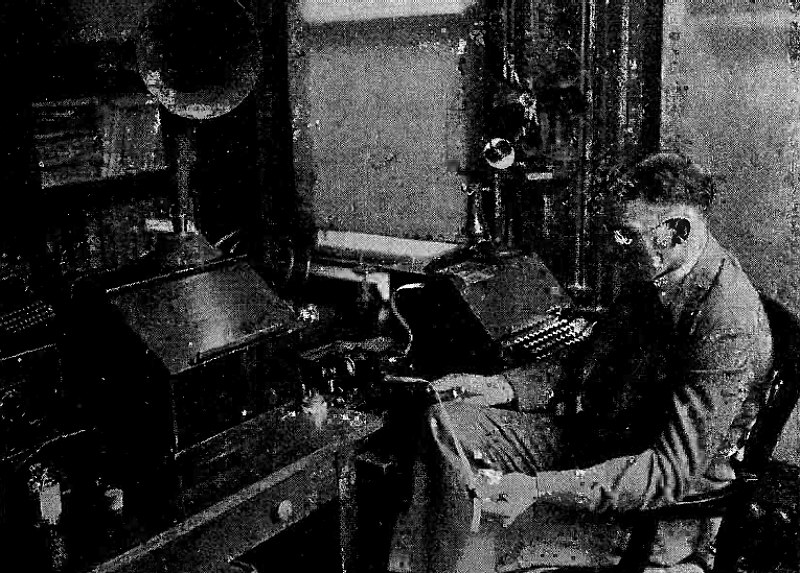
Radio Operating Room at Los Angeles Station.
Article:Radio Plane Dispatching.
"The greatest practical use of radio in aviation, as yet, is in plane dispatching. The wire telegraph, that indispensable aid to train dispatching, is not as available to the new companies which operate regular airplane service as it is to the railroads. So several of them are using radio telegraphy instead..."
(Radio for February, 1928)
Inauguration of Aircraft Radio Beacon at College Park, Md., by Dr. George K. Burgess, Director of U. S. Bureau of Standards.
Article: Radio Guidance of Aircraft. A Summary of Tests as to the Effectiveness of the Crossed Coil Radio Beacon for a National Airway System.
"Not until the development of the crossed coil radio beacon were coil antennas found to be practical equipment on airplanes for determining the bearings of radio stations. The great amplification needed with small coils gave a high noise level that prevented any close observation of the minimum signal during rotation of the coil when the usual form of radio compass was employed. And various other methods also proved impractical until crossed coil beacons were installed at several stations in the East and West..."
(Radio for February, 1928)
KFLF Wireless Room with Operator L. Elden Smith at the Key.
Article: KELF.
"You have read of the amateur radio operator's deeds of distance, daring and discovery. He can truly say: "The world's mine oyster-even with low power," as his activities are confined only by the physical limits of the earth. The amateur has rushed to the rescue during times of emergency in peace and in war, establishing communication by, radio where other methods failed. He has discovered the great possibilities of short waves and has made countless experiments for the benefit of the science. These activities more or less spectacular, have drawn public attention and admiration by their strikingly unusual aspects, while other worthy accomplishments are unnoticed; except by the amateur "fraternity," perhaps. The following story is one of an amateur operator's devising, determination and dependability. While lacking in much of the sensational, it is accompanied by the satisfaction of having contributed to the large list of amateur radio achievements..."
(Radio for February, 1928)
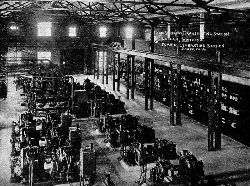
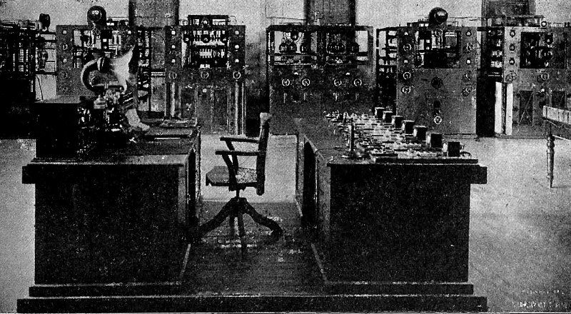
Diesel -Driven Generators and Switchboard for Beam Station at Bailan, Victoria, Australia.
Article: What is the Marconi "Beam"? An Explanation of its Functioning and a Description of the Australian Installation For Short Wave Communication With England.
"Ever since Senatore Marconi created such a profound impression several years ago with the announcement that he had developed a directional communication system concentrating all its energy into one narrow beam, there has been a keen desire in technical circles to learn something about the actual modus operandi of this new transmission development, and its reliability on commercial schedules as compared to existing systems. When the opportunity was afforded me therefore to visit Australia, and view at first hand the mysterious circuits about which so much was heard and so little really known - it meant the culmination of a desire which I suppose most transmission engineers fostered, and one I had myself only remotely expected to have gratified..."
(Radio for March, 1928)
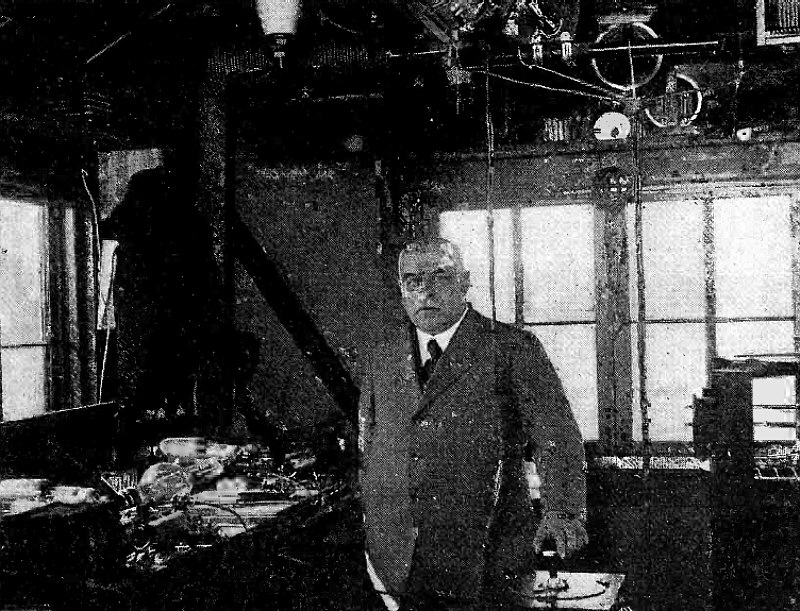
Short Wave Transmitters at 3L0, Melbourne, Showing Copper Strips Around Power Tubes for Equal Heat Dissipation and Equi -Potential Strain.
Article: What is the Marconi "Beam"? An Explanation of its Functioning and a Description of the Australian Installation For Short Wave Communication With England.
(Radio for March, 1928)
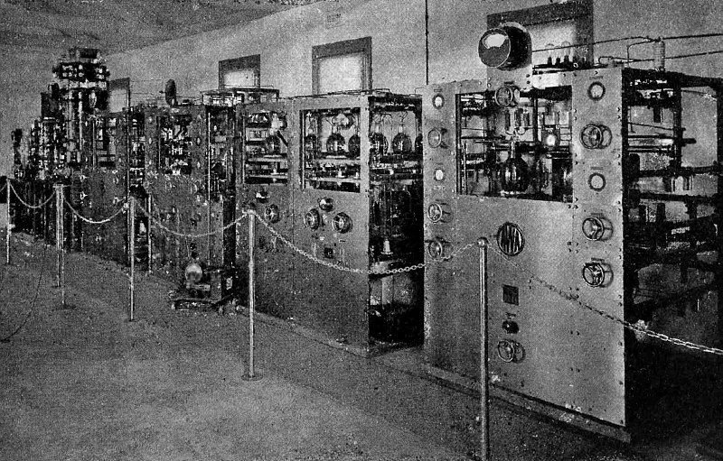
5 KW. Beam Transmitter at Radio Central, Pennant Hills, Sydney, Showing brass Pannels and Support Frames.
Article: What is the Marconi "Beam"? An Explanation of its Functioning and a Description of the Australian Installation For Short Wave Communication With England.
(Radio for March, 1928)
Two -Tube Kit as Modified for Screened Grid Tube.
Article: Radio Kit Reviews. Adapting The Browning - Drake Two - Tube Kit To The Shielded Grid Tube.
"The new double grid tube can be used in the r.f. stage of the Browning -Drake two -tube kit described in January RADIO by a few simple changes..."
(Radio for March, 1928)
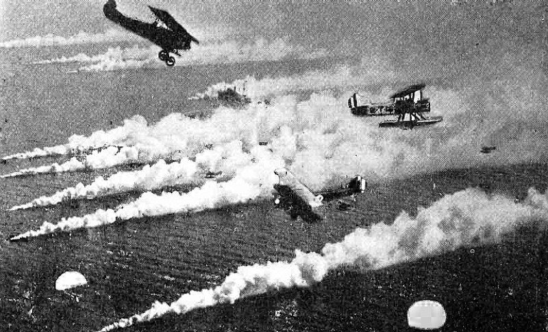
Radio -Directed Attack by Torpedo Planes on Ships Concealed in Smoke. A Torpedo Plane (Right) Is Escaping a Fighter (Upper Left) Which Is About to Attack a Bomber (Lower). Two Parachutes Are Proceeding Seawards.
Article: Radio -The Aladdin of The Navy.
"With the recent announcement that the Navy is interested in the development of a system of transferring pictures by radio from scouting aircraft direct to commanding admirals afloat, attention of radio enthusiasts again has focussed on the sea and air services. Though it is not generally known, the Navy was the prime mover in the development of the transmission of pictures by radio, as it was in the development of radio telephony and, still earlier, of radio telegraphy..."
(Radio for April, 1928)
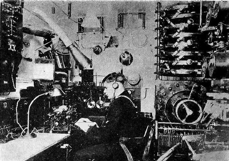
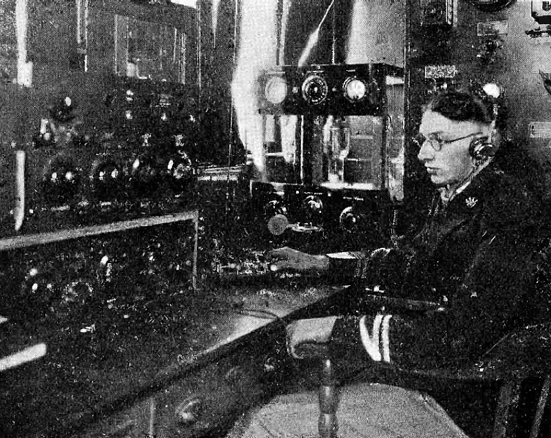
Interior of a U S. Destroyer Radio Room.
Article: Radio -The Aladdin of The Navy.
(Radio for April, 1928)
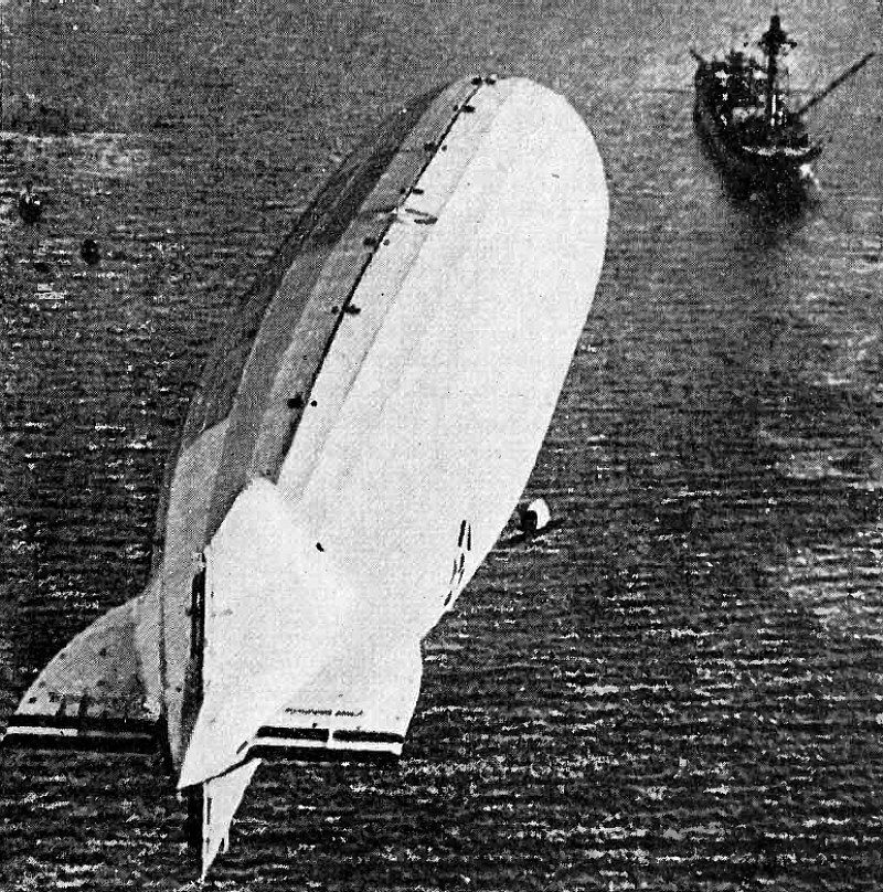
Radio - Directed Anchorage of Dirigible to Sea -Going Mooring - Mast.
Article: Radio -The Aladdin of The Navy.
(Radio for April, 1928)
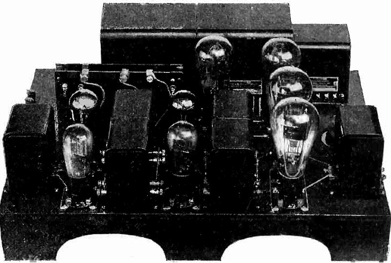
Top View of Audio Amplifier Section.
Article: the Balanced Impedance A. C. Tube Receiver. Constructional Details of An Interesting Experimental Six -Tube Model Having Excellent Sensitivity.
"This circuit combines the convenience of a receiver operated directly from alternating current socket power with the advantage of obtaining even sensitivity throughout the entire broadcast band. It can be applied to most tuned r.f. receivers employing two or three stages of r.f. amplification. The circuit is published for the benefit of the experimenter rather than the person interested only in what he hears. Consequently considerable latitude is allowable in the choice of parts..."
(Radio for April, 1928)
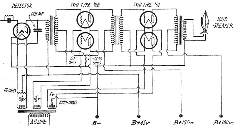
Circuit Diagram of Audio Amplifier With A.C. Tubes.
Article: the Balanced Impedance A. C. Tube Receiver. Constructional Details of An Interesting Experimental Six -Tube Model Having Excellent Sensitivity.
(Radio for April, 1928)
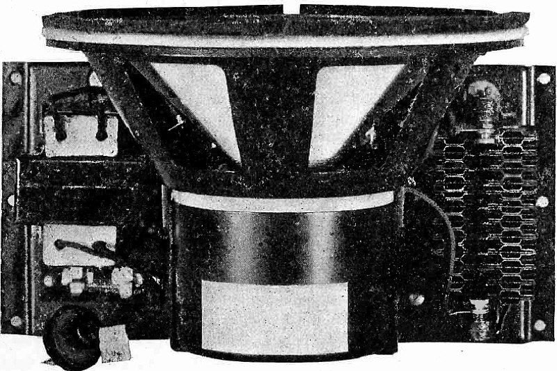
A. C. Electro -Dynamic Speaker.
Article: The Electro -Dynamic Speaker. A Complete Explanation of Its Principles of Action, Design, Installation and Performance.
"The action of the modern electrodynamic speaker depends upon the movement of the surrounding air by a paper cone whose apex is attached to a moveable coil placed in the field of a strong electro -magnet. The coil carries the output from a radio receiver or other device producing variations in electrical current corresponding to variations in the sound which is to be reproduced. The reaction between the electromagnetic fields of the moveable coil and the fixed electro -magnet moves the small coil which actuates the paper cone so that the frequency and amplitude of its movement corresponds to the tone and intensity of the sound which is heard..."
(Radio for May, 1928)
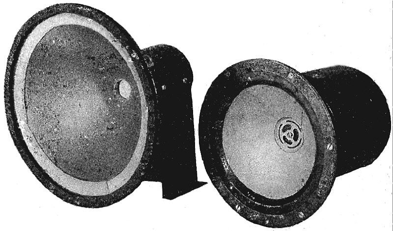
Two Types of Electro -Dynamic Speakers.
Article: The Electro -Dynamic Speaker. A Complete Explanation of Its Principles of Action, Design, Installation and Performance.
(Radio for May, 1928)
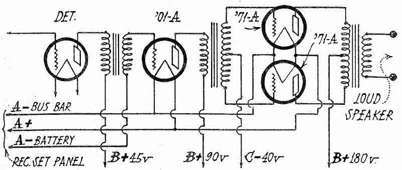
Push - Pull Amplifier for 115 K. C. Superheterodyne.
Article: Queries and Replies.
"Would like a circuit for a two -stage audio amplifier to be used in connection with the Best 115 k.c. super, but using a push-pull power stage, with 71A tubes and 180 volts "B" supply.."
(Radio for May, 1928)
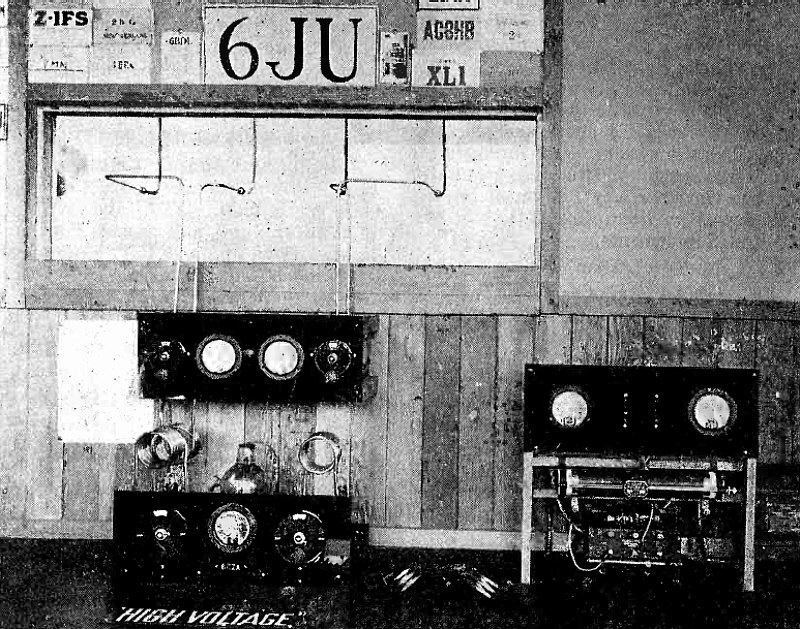
Short Wave Transmitter at 6JU.
Article: With the Amateur Operators.
"The amateur station of the San Mateo Junior College Radio Club, at San Mateo, Calif., has a location to be envied by most amateurs. The "shack" is a three-room house built on top of the three-story main building of the college. It consists of an operating room, a club room, and a generator room..."
(Radio for May, 1928)
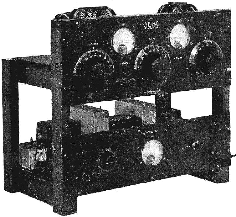
Front View of Aero Radiophone Transmitter.
Article: Radio Kit Reviews.
"This is a complete short-wave transmitter for either phone or C.W. which may be assembled from standard parts at a cost of about $150, exclusive of tubes and microphone. It is designed for socket -power operation and is rated at 7.5 watts at 550 volts..."
(Radio for May, 1928)
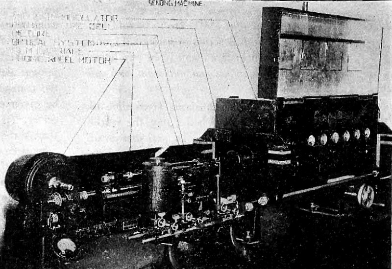
Equipment at Sending End of Motion Picture Transmission.
Article: Telephoto Transmission of Motion Pictures.
"Public interest in telephone transmission of photographs was aroused recently by an announcement by the Bell System that motion pictures had been sucessfully transmitted between Chicago and New York over the long distance telephone wires. This news is of interest to radio experimenters in the telephotograph field, especially in view of the tremendous increase in the past year of the amateur motion picture fad, so that we can foresee the day not far distant when experimenters will be receiving sections of amateur motion pic- ture scenes by radio, thus opening up another field into which radio and photography are interallied..."
(Radio for June, 1928)
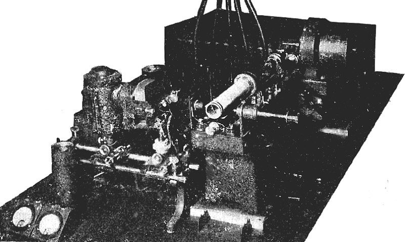
Receiving Equipment of Commercial Telephoto Installation.
Article: Telephoto Transmission of Motion Pictures.
(Radio for June, 1928)
Automatic Code Transmitter for Broadcasting Information from Weather Bureau.
Article: Weather Service for Aviators.
"The $2,705,000 appropriation for the Weather Bureau of the United States Department of Agriculture contains a fund of $15,320 for a special meteorological service by radio for the benefit of aviators. This increase in the budget is in recognition of the plans of the Weather Bureau to continue its aviation forecast service from its central office in Washington and branch office in San Francisco..."
(Radio for June, 1928)
Short Wave Transmitter at 2XE.
Article: Radio Kit Reviews.
"Radio U-2XE, owned by A. H. Grebe Company at Richmond Hill, N. Y., and constructed by Wm. Schick, a Grebe engineer, broadcasts WABC programs on 58.5 meters. It is designed with quartz crystal control to have constant wavelength not withstanding swinging of the antenna or changes in plate or filament voltage..."
(Radio for June, 1928)
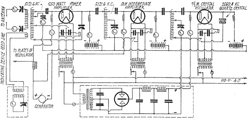
Circuit Diagram of Short Wave Transmitter at 2XE.
Article: Radio Kit Reviews.
(Radio for June, 1928)
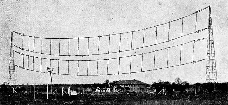
Short -Wave Telephone Transmitting Station at Deal, N. J.
Article: The Short -Wave Trans -Atlantic Radiophone.
"A regular radiotelephone service on short waves between the United States and England is soon to be in effect. This is a departure in that two-way communication is to be attempted on short waves, instead of the long waves by means of which the service was introduced. The Bell Telephone Laboratories, Inc., recently erected buildings and installed short-wave receiving equipment at Netcong, New Jersey, and the British Postoffice has completed a short-wave transmitting station in Scotland..."
(Radio for November, 1928)
Short -Wave Receiving Station at Netcong, N. J.
Article: The Short -Wave Trans -Atlantic Radiophone.
(Radio for November, 1928)
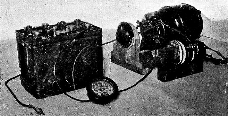
Complete Charging Outfit.
Article: Battery Charging with a Synchronous Rectifier. Complete Details Regarding the Construction and Operation of a Synchronous Rectifier.
"Asynchronous rectifier is an excellent source of high potential d.c. for transmitting, as testified by the many "syncs" owned by amateur operators. Such a rectifier, as may be known, utilizes a synchronous motor, a commutator disc, and a brush rigging. The commutator is rotated in step with the alternating current, and functions as a switch, reversing at the correct instant so as to bring the output voltage right side up. In its ùse for high -voltage, full -wave rectified supply it is eminently satisfactory. With a small amount of care it will function just as satisfactorily to deliver several amperes at comparatively low voltages..."
(Radio for November, 1928)
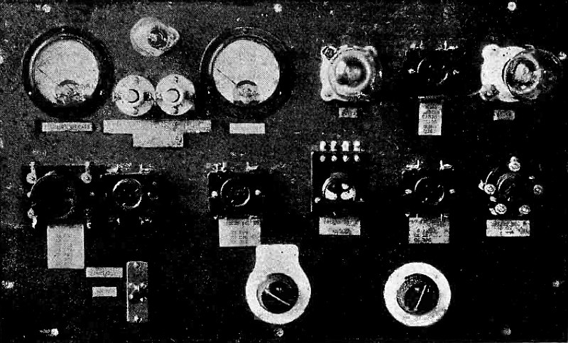
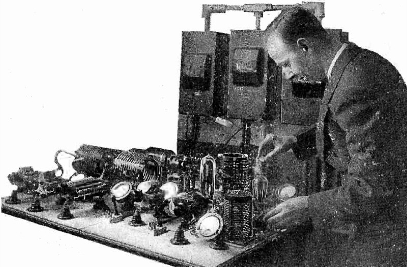
Panel View, showing Arrangement of Sockets and Meters.
Article: A Complete Tube Testing Set.
"While a number of tube testers have been described in past issues of RADIO, there have been none so complete in the number of possible tests which can be made, as the one described herewith. This tester was made up from suggestions contained in a tube data book recently published by E. T. Cunningham, Inc., and with it, the service man, experimenter or tube salesman can tell practically everything necessary about the condition of any of the standard tubes..."
(Radio for November, 1928)
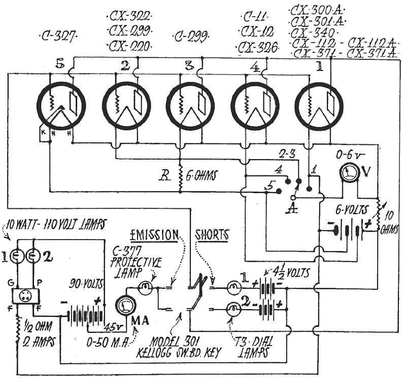
Circuit Diagram of Complete Tube Tester.
Article: A Complete Tube Testing Set.
(Radio for November, 1928)
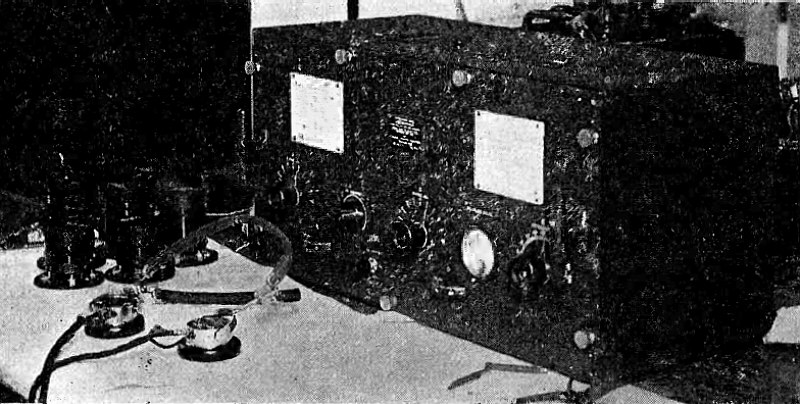
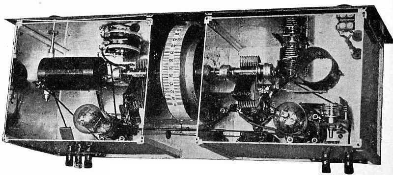
Marshall Short -Wave Receiver, as Used by Navy.
Article: The Marshall Short -Wave Receiver. A New Short -Wave Circuit Developed for the Navy and Using Screen -Grid Tubes.
"New high -frequency receiving set designed and built at the Bellevue Naval Research Laboratory incorporates the screened -grid or four -element electron tube. This receiver, intended for use on battleships and other floating units as well as at shore stations of the United States Navy, marks the introduction of a push-pull, screened -
grid type of receiving set in the Government service-a type of amplifier already popularized by broadcast listeners and radio amateurs. However, this novel circuit is said to be the most sensitive yet developed by the Navy for high frequencies..."
(Radio for November, 1928)
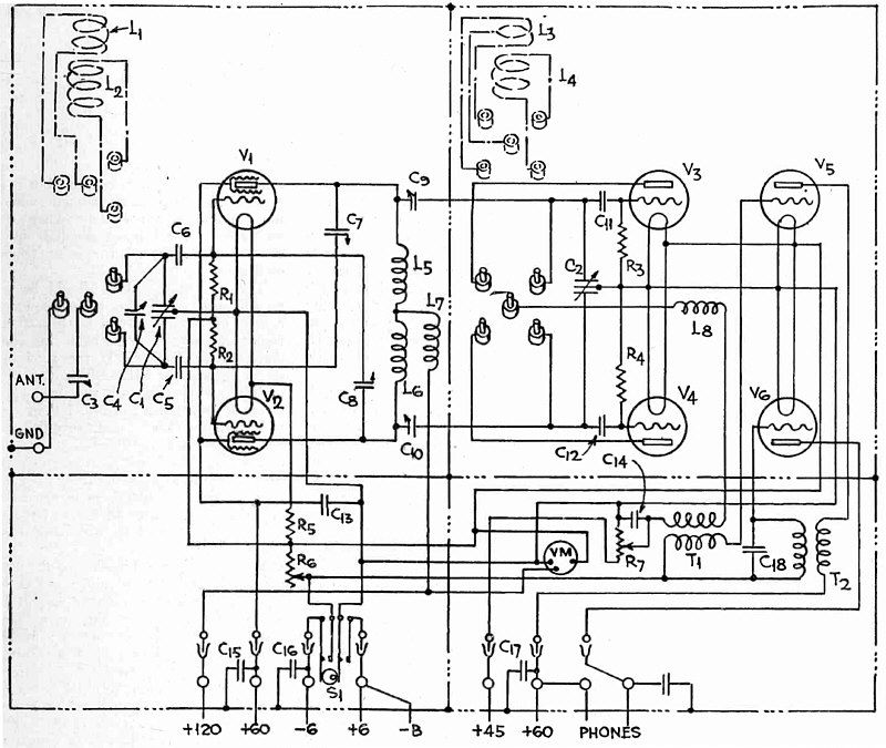
Circuit Diagram of Marshall Short -Wave Set.
Article: The Marshall Short -Wave Receiver. A New Short -Wave Circuit Developed for the Navy and Using Screen -Grid Tubes.
(Radio for November, 1928)
Build this modern amplifier at Low Cost!
(Radio for November, 1928)
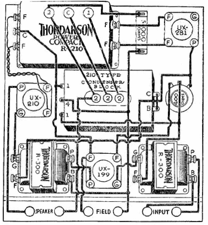
Pictorial Wiring Diagram of Thordarson Phonograph Amplifier.
Article: THORDARSON PHONOGRAPH AMPLIFIER.
"This two -stage all -electric amplifier using a 210 power tube, converts an old style mechanical phonograph into a modern high quality electrical reproducing machine. In addition to the revolving turntable and electrically recorded records, it requires only a good pick-up unit and the easily assembled equipment listed in this kit to get faithful reproduction of audio frequencies from any good radio speaker..."
(Radio for November, 1928)
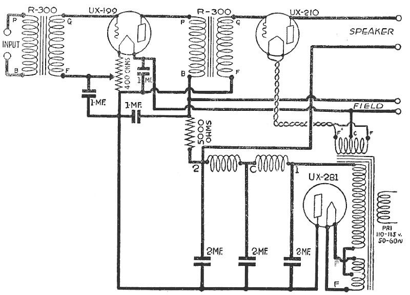
Circuit Diagram of Thordarson Phonograph Amplifier.
Article: THORDARSON PHONOGRAPH AMPLIFIER.
(Radio for November, 1928)
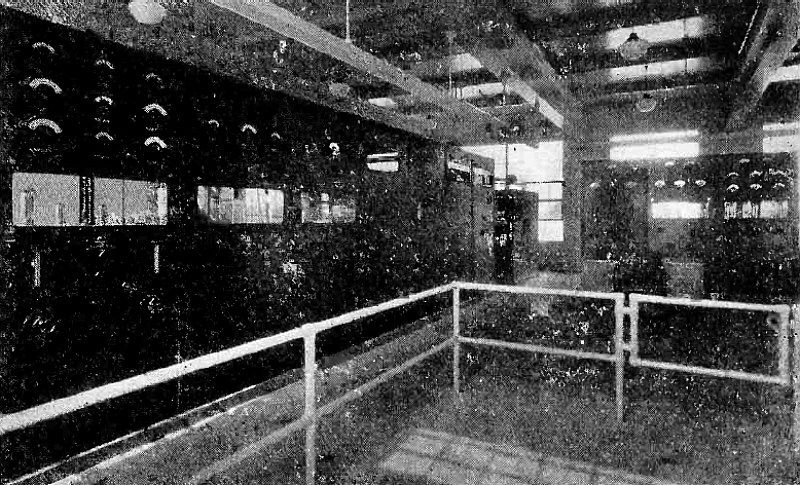
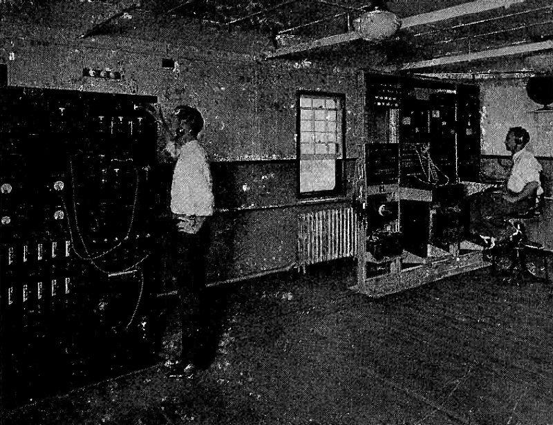
Control Room at WLW.
Article: WLW'S 50,000 -Watt Transmitter.
"Nation-Wide reception of WLW's new 50,000 -watt transmitter at Mason, Ohio has aroused interest in the equipment whereby this was made possible, especially as it contains several innovations in the standard Western Electric apparatus. These changes include 100 per cent modulation of the carrier instead of the customary fractional modulation, a harmonic filter, and an especially effective antenna ground system..."
(Radio for December, 1928)
Amplifier and Modulating Unit.
Article: WLW'S 50,000 -Watt Transmitter.
(Radio for December, 1928)
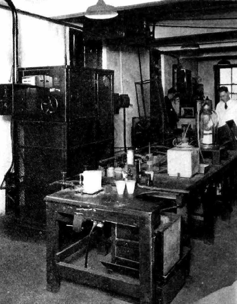
Typical Installation of Small High Frequency Furnaces.
Article: High Frequency Electric Furnaces. Methods and Equipment Used for Melting Alloys for Dental Use.
"A real field of application for the high frequency induction furnace has been found in the melting of precious metals and their alloys for dental use. Although this has been picturesquely advertised as "melting by radio" it is merely another industrial application of the high frequency current which is also used for radio transmission. The output of a high frequency generator is connected directly to an induction coil whose electromagnetic field is intercepted by the material to be melted, this being placed within the coil. The eddy currents thus produced are effective in heating the material to very high temperatures..."
(Radio for December, 1928)
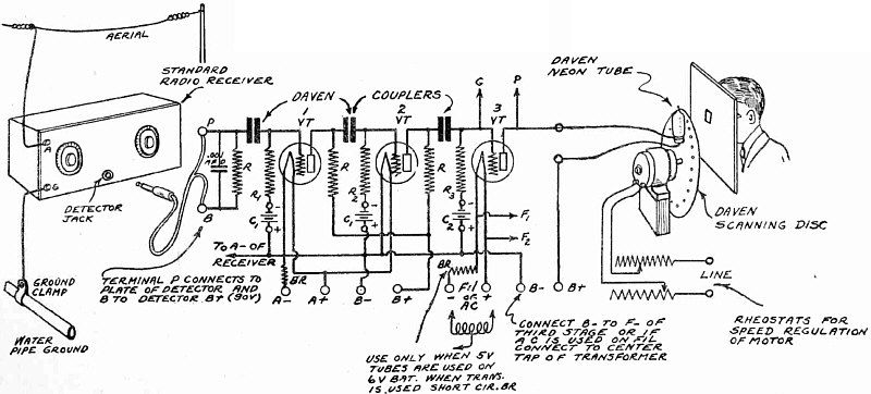
Circuit Diagram of Daven Television Amplifier.
Article: Radio Picture Transmission and Reception. Photoelectric Equipment and Methods for Visual Communication.
"The first consideration that governs the construction of a television receiving outfit is the character of transmissions which are available for reception. Whether they are on long or short wavelengths will not only determine the type of radio receiver, but also, usually, the size of scanning disc. The 24 -line pictures are ordinarily transmitted on the regular broadcast wavelengths and the 48 -line pictures in the short-wave carriers..."
(Radio for December, 1928)
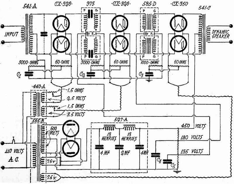
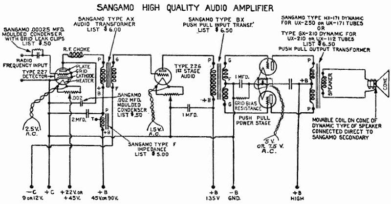
Circuit Diagram of the Power Amplifier.
Article: Radio Kit Reviews. AN AUDITORIUM POWER AMPLIFIER AND DYNAMIC SPEAKER.
"This outfit is designed for those who want good quality of reproduction at very great volume. The voltage amplification of each stage furnishes the correct input to the following stage, thus allowing all tubes to work at their normal capacities. Push-pull amplification has been used in all three stages, not only to increase the amplification, but also to minimize the a.c. hum..."
(Radio for December, 1928)
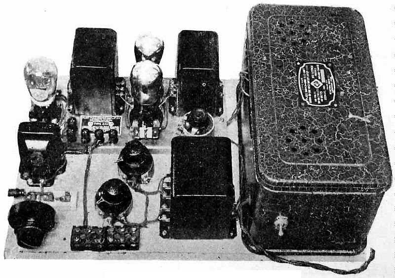
350 Push-Pull Amplifier.
"Here is a de luxe power amplifier and "B" eliminator using General Radio apparatus of the finest kind to reproduce voice and music of majestic tonal qualities with volume sufficient to fill the largest auditorium. Ideal for outdoor demonstrations, theatres, dance halls and large homes. It is a custom-built amplifier. Accurately wired, balanced, tested and guaranteed in every respect. Push -Pull throughout in all three stages."
(Radio for December, 1928)
")
")
")
")
")