Eng. Konrad Widelski
All About Electric Guitar - Part II
Radioamator i Krótkofalowiec Polski, Year 16, October 1966, No. 10
The first part of the article (no. 9/66) provides a description of a simple amplifier based on two electron tubes. This amplifier, properly made, will fully satisfy the guitarist's needs. Nevertheless, its power in some cases (in larger rooms, especially for a bass guitar) may turn out to be insufficient. Therefore, for more advanced radio amateurs, we present a design description of the amplifier in a push-pull circuit with an output power of 12W. Of course, the construction of such an amplifier should be started only by radio amateurs who already have some positive achievements in the field of amplifiers, because building this device on one's own is not easy.
PUSH-PULL AMPLIFIER
The amplifier was assembled from a minimal number of elements, quite easily available on the market. Only the output transformer should be made by yourself, as it is untypical and cannot be bought.
The amplifier has very good - considering amateur requirements - parameters. They have been achieved by simple means, namely the use of a negative feedback system at several points and direct feedback between the stages.
Figure 9 shows a schematic diagram of the amplifier. As you can see, the number of tubes and elements has been significantly reduced to a minimum. One of the ECC83 electron tube triodes works in the first stage. The anode of this vacuum tube is directly connected to the control grid of the next amplifier stage. This stage, equipped with the second triode of the ECC83 electron tube, works in a phase inverting system.
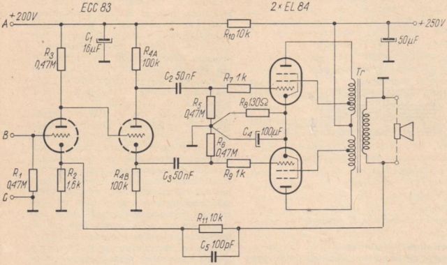
Fig. 9. Schematic diagram of the 10W amplifier
The phase reversal system used (the so-called "cathodine") is reliable in its simplicity. The output stage uses a pair of EL84 type tubes. Of course, in line with the requirements of modern Hi-Fi technology, this stage uses negative feedback in screen grids (the so-called "ultralinear system"). These grids are not connected - as is usually the case - directly to the high voltage source, but to special taps on the primary winding of the output transformer. The use of such feedback complicates the production of the output transformer somewhat, but it is very cost-effective as it reduces the nonlinear distortion caused by the power stage by about two times. In addition, the entire amplifier is subject to deep feedback, which runs from the secondary winding of the output transformer to the cathode of the pre-amplifier (the left triode system in the diagram). The implementation of the feedback covering the entire amplifier is possible, among others, thanks to the direct coupling of its first two stages.
The following parts and components are needed to make the amplifier:
- Electron tubes
- V3, V4 - EL84 - 2 pieces
- V2 - ECC83 - 1 piece
- Resistors
- R1, R5, R6 - 0,47MΩ/0,1W - 3 pieces
- R2 - 1,6kΩ/0,25W - 1 piece
- R3 - 0,47MΩ/0,5W - 1 piece
- R4A, R4B - 100kΩ/0,5W - 2 pieces
- R7, R9 - 1kΩ/0,1W - 2 pieces
- R8 - drutowy - 130Ω/3W - 1 piece
- R10 - 22kΩ/0,5W - 1 piece
- R11 - 10kΩ/0,1W - 1 piece
- Capacitors
- C1 - electrolytic - 16μF / 350V - 1 piece
- C2, C3 - styroflex - 50nF / 250V - 2 pieces
- C4 - electrolytic - 100μF / 15V - 1 piece
- C5 - ceramic - 100pF - 1 piece
- C6 - electrolytic - 50μF / 350V - 1 piece
- Tr - output transformer (as per description).
Readers will be surprised by the marking of the R4A and R4B resistors. We marked it this way because it is, in fact, a working resistor in the amplifier's second tube stage, divided in half. One half is in the anode circuit and the other half is in the cathode circuit of the vacuum tube. Thus, in this step, two voltages of the same amplitude are obtained (because the resistors are connected in series). The voltages also have opposite phases and can therefore be used to drive the push-pull power stage.
For the correct operation of the phase inversion stage, however, it is necessary that the resistances of the two mentioned resistors are the same. Otherwise, the voltages applied to the power stage control grids will not be equal. The required accuracy is approximately 1%. It should be clarified that in this case the point is not that both resistors should have a resistance equal to exactly 100kΩ; this resistance can be in the range of 90 ÷ 110kΩ. However, both resistors should have exactly the same resistance - within the limits given above. They should therefore be selected using an accurate ohmmeter or bridge.
Fabrication of the output transformer
The output transformer is usually the most troublesome. However, it is worth making maximum efforts to manufacture this element, because the quality of the transformer is to a large extent dependent on the quality parameters of the amplifier.
To make the transformer, you need a core with a diameter of the middle column of approximately 9 ÷ 10cm2. According to the core dimensions, the transformer body should be symmetrically divided into half. If we have a factory-made body for a given core, an additional central partition should be installed in it (Figure 10).
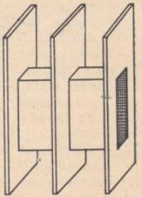
Fig. 10. Body for symmetrical output / loudspeaker transformer winding
The winding of the output transformer for a push-pull circuit should be wound with as much symmetry as possible. Therefore, its windings are divided into appropriate sections for the left and right parts of the body. It is not difficult to correctly wind such a transformer. The greatest difficulty for those who do not know this issue, however, is the exploration of the principle of symmetrical winding of individual winding sections. Therefore, among the many possible ones, one of the simplest winding arrangements has been used, which, despite its simplicity, provides good results. The diagram of the transformer windings is shown in Figure 11.
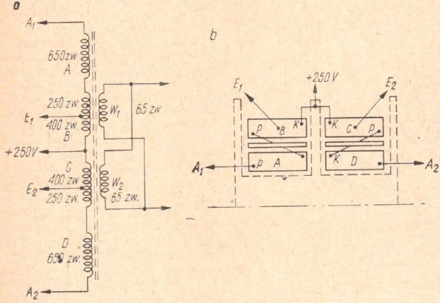
Fig. 11. Winding of the output transformer
a - schematic diagram, b - symmetrical arrangement of individual sections; for the sake of simplicity, it is shown that the sections of only the primary winding are connected
The primary winding consists of 4 sections, each with 650 turns of enamel wire Ø0.16mm. In two sections there are additional taps for supplying the screen grids. Both sections of the winding belonging to the anode circuit of one of the output tubes (from + 250V to the anode of the tube) are located in the same half of the transformer body. Between these sections there is (in each half of the body) a secondary winding section wound with an enamel Ø0.5 ÷ Ø0.6mm wire.
In order to maintain the symmetry of the transformer windings, the individual sections should be wound in the same way as shown in the P (beginning of the winding) and K (end of the winding) marks. This means that if we start winding the first section of the anode winding A (lower, closer to the transformer core) on the bottom of the body from the outer side, and finish at the inner side (i.e. at the central partition), then the analogous section D for the second electron tube should be wound on in the same direction, i.e. starting from the central partition (at the same height as the last layer of section A) and ending at the bottom of the body to the outside (Figure 12).
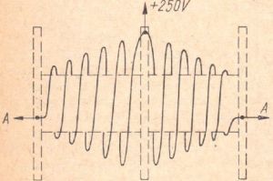
Fig. 12. A simplified sketch of the symmetrical winding of a loudspeaker transformer
Only such a design of two sections (for example, two halves of an anode winding) enables full symmetry to be obtained: both anodes of the tubes are connected to identically located ends of the winding, and also the common point (center of the winding) is the connection of two identically located ends. In this situation, the inductances of the windings are the same for both sections (as long as the same number of turns in the sections is kept), their resistances (the same number of conductors), the capacitance of individual winding points (e.g. anodes of electron tubes) to ground (core), etc.
However, such a winding is impracticable in practice; it is not possible to make the second part of the winding (section D) "from end" as described, i.e. from the top of the winding to its bottom. Therefore, we act differently: after winding section A, we start winding section D (Figure 12) also from the outer extreme point and we wind it higher and higher, ending it at the middle partition. In order for the whole winding to be wound in one direction, the second section should be wound from the end in the opposite direction. It is probably understandable from Fig. 12, where, for ease of use, a multilayer (thick) winding is presented in the form of a single, increasingly "thicker" spiral. Similarly, we wind a more complicated winding, in our case a 4-section winding.
The secondary winding is made in two sections, one in each half of the transformer body. The windings are connected in parallel, with the ends in the same position being connected to each other for symmetry (Figure 13). Therefore, as shown in this figure, both sections of the secondary winding should be wound in opposite (arbitrary) directions.
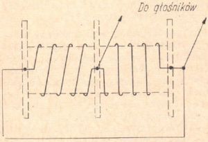
Fig. 13. Schematic diagram of the winding and connection of the secondary winding section of the transformer
Thick spacers should be used between the individual winding sections. All the ends of the windings should be led outside the body, and the joining of the sections should be done in the last phase of work. A little more attention should be paid only to the execution of the last two sections of the primary winding (top windings), from which the taps are led out to supply the screening grids. We output them according to the winding diagram - after making 400 turns of both the right and left winding sections.
When connecting the ends of the winding led to the outside, it is necessary to check the correctness of its execution once again. The easiest way to do this is to follow the winding sequence from the anode of one vacuum tube to the anode of the other tube one by one. There is a general rule that applies to all output transformers, regardless of the method of sectioning its winding: the primary winding wire should run after proper winding and connection of individual sections of this winding in any, but invariably, one direction from one anode of the electron tube to the other.
It is worth adding that most of the failures encountered by designers of push-pull amplifiers result from improper winding of the output transformer. One wrong connection or wrong winding of any section of the winding inevitably leads to a completely defective operation of the amplifier.
Preamplifier
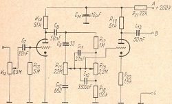
The sensitivity of the discussed amplifier is not high, therefore, to ensure proper cooperation with an electric turntable or guitar, it is necessary to use a preamplifier. The diagram of the appropriate preamplifier is shown in Figure 14. It is a classic circuit with an ECC83 electron tube with low and high tone equalizers between both stages.
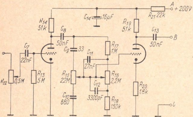
Fig. 14. Schematic diagram of the preamplifier
The potentiometer at the input of the circuit is used to adjust the volume, and the next one - to adjust the bass, with the upper position of the slider emphasizing the bass. The third potentiometer controls treble; in the upper position of its slider, the treble is emphasized. For frequencies around 1000Hz, the damping introduced by the system is more or less constant, regardless of the setting of both potentiometers. This damping is covered (with some surplus of course) by the amplification stages.
The following parts and components are required to make the preamplifier:
- Electron tube V1 - type ECC83 - 1 piece
- Resistors
- R12 - logarithmic potentiometer 0.5 ÷ 1MΩ - 1 piece
- R13 - 5MΩ/0,1W - 1 piece
- R14, R19 - 51kΩ/0,5W - 2 pieces
- R15, R16 - linear potentiometer 2.2MΩ - 2 pieces
- R17 - 1MΩ/0,1W - 1 piece
- R18 - 150kΩ/0,1W - 1 piece
- R20 - 1,8kΩ/0,25W - 1 piece
- R21 - 22kΩ/0,5W - 1 piece
- Capacitors
- C7 - styroflex 22nF / 250V - 1 piece
- C8, C13 - styroflex 50nF / 250V - 2 pieces
- C9 - ceramic 680pG - 1 piece
- C10 - ceramic 680pF - 1 piece
- C11 - styroflex 27nF - 1 piece
- C12 - styroflex 3300pF - 1 piece
- C14 - electrolytic 16μF / 375V - 1 piece
- In addition, small assembly elements, such as: an electron tube socket, input sockets, etc.
The diagram of the preamplifier with tone equalizers is shown separately because it can be set up as an independent stage. Amateurs often assemble such a preamplifier separately and place it in a place where the control knobs of the apparatus are easily accessible. This is possible because the preamplifier is relatively small. The power amplifier, on the other hand, may be located elsewhere. However, the distance between the preamplifier and the amplifier must not be too large (maximum 0.5 ÷ 1.0 m), because if the shielding wire used to connect the B-B points of both elements is too long, the treble would be weakened too much. For this reason, it is best to assemble the preamplifier and the amplifier in the form of a unitary unit, as it will be given later in the description. Needless to say, when putting together the two parts of the apparatus discussed, appropriate points of the system should be connected with each other (Figures 9 and 14), namely A-A, B-B and C-C.
Power supply
Making an amplifier's AC power supply as a separate component is rarely practiced, although it is one of the simplest ways to avoid the hassle, noise, etc. problems that can occur in a compact design. Therefore, for all less advanced users, it is recommended to build the power supply on a small, separate "chassis". Its diagram is shown in Figure 15.
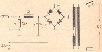
Fig. 15. Schematic diagram of the power supply
The following components are needed to make the power supply:
- R - resistor 100kΩ / 1W - 1 piece
- C - electrolytic capacitor 50μF / 450V - 1 piece
- Pr - rectifier SPS-6B-250-85 (or similar) - 1 piece
- Dł - choke (as per description)
- Tr - mains transformer from the "Tatry", "Bolero", "Karioka", "Rumba", "Sonata" receivers - 1 piece
- W - switch (any type)
- Small assembly elements, such as: socket with a 0.4A fuse, connector (from the socket and tube socket, octal type), two-core cord with a plug, etc.
As a choke you can use any choke from a TV or radio set, wound with a wire with a diameter not less than 0.25mm. Who would like to make the elements of the power supply on their own can use the following data:
- Mains transformer:
- cross-section of the central column of the core: about 9 cm2,
- primary winding 220V: about 1250 turns of Ø0.4mm wire,
- secondary winding: approx. 1350 wire turns Ø1.2 ÷ 1.5mm.
- Filter choke:
- cross-section of the central core column: about 3 ÷ 4 cm2,
- winding: 1000 ÷ 2000 wire turns Ø0.25 ÷ 0.30mm.
MOUNTING THE AMPLIFIER
You should start assembling the amplifier "from the end", that is, from making the power supply. Figure 16 shows, for example, one of the simplest mechanical solutions for this part of the apparatus: the base (aluminum or iron sheet) has only two side walls. In one of them there is a power cord and a fuse, in the other - an "octal" socket serving as a connector plug.
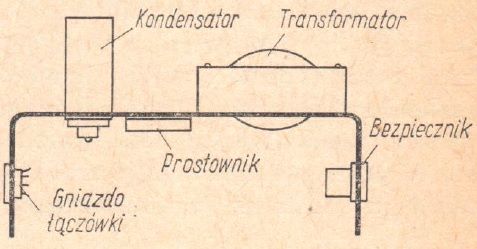
Fig. 16. An example of the mechanical design of the power supply
Particular attention should be paid to a solid connection to the rectifier base plate (in Figure 16 - under the choke), so that through good contact between the rectifier housing and the base, excess heat can be removed from the rectifier elements.
After assembling the power supply, check its operation immediately; for this purpose - after switching the system on, use a suitable instrument to check the voltage between the contacts of the octal socket.
The same tube stand is mounted in the wall of the amplifier chassis. In this case, the connection between the power supply and the amplifier will require an appropriate connector, ie four cables braided together in plastic mattings, terminated with plinths removed from old "octal" electron tubes. Figure 17 shows an example of a connection diagram of such a terminal block.
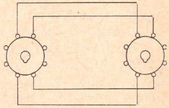
Fig. 17. Schematic diagram of the power supply-amplifier connector
Since we made the power supply as a separate component, the arrangement of elements in our amplifier is not critical and can be almost any. Of course, by the term "arbitrary" we understand some, at least somewhat sensible, positioning of the essential elements, ie such that the lines connecting these elements are not unnecessarily long. An example of the arrangement of the essential parts of the amplifier is shown in Figure 18. Of course, its close copying is not necessary.
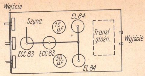
Fig. 18. An example of the arrangement of the essential elements of an amplifier
We start, of course, the assembly of the amplifier from the filament circuit. Less advanced people should use all the remarks on this subject when assembling the circuit and checking it, provided in the detailed discussion of the assembly of the amplifier from part I (in issue 9/66). These notes are very relevant to amateur amplifiers of all types. The remarks regarding the experimental determination of the method of connecting negative feedback are equally valid.
Let's discuss the so-called "symmetrization" of the heating circuit. This treatment is aimed at minimizing the hum coming from the filament circuit of the electron tubes. In order to eliminate it, both filament wires should be connected to ground (earthing bar) through resistors of 47 ÷ 100Ω resistance. Slightly better results can be obtained by connecting the ends of the mentioned resistors not to the ground of the system, but to the cathodes of the electron tubes of the amplifier output stage, from where the entire heating circuit will obtain (in relation to ground) a positive voltage of a few volts.
SPEAKER SET AND AMPLIFIER TESTS
The output transformer of the amplifier is designed to be loaded with a resistance of about 5 Ω. Of course, it is not necessary to fine-tune this resistance. The amplifier will also work slightly worse when loaded with a loudspeaker (loudspeaker set) with a resistance in the range of 3.5 ÷ 7.0Ω. Since the maximum power of the amplifier is about 10 ÷ 12W, the total power of the set should be within the range of 15 ÷ 20W. Such a set is best made in the form of a sound column set up, for example, from ten 2-watt or 3-watt speakers. We will talk about building a loudspeaker set yourself in the last, third part of the article.
The first attempts of the amplifier are best carried out with an electric turntable and a good gramophone record. When playing a recording from a vinyl record, you should check the operation of individual amplifier controls, i.e. the gain controller and two tone controls. No hum should be heard from the speakers with the gain control in the leftmost position (shorted input). Only a slight, barely audible noise is allowed.
The sensitivity of the amplifier is sufficient for cooperation with an electric turntable. The output voltages of electric guitars may in some cases prove to be insufficient for full drive. In such a case, a transistor preamplifier, the design description of which is given in part I, should be built into the guitar.
The sensitivity of the amplifier can be further adjusted by selecting the value of the resistor R11. With a value of this resistor greater than 10kΩ, the sensitivity of the circuit increases. The maximum value of this resistor should not, however, be higher than 30 ÷ 50kΩ, it is also not advisable to use a resistance lower than 8 ÷ 10kΩ. The sensitivity of the circuit can be additionally reduced by including the first stage gain of a resistor in the cathode circuit of the electron tube with a value in the range of 0.5 ÷ 2.0kΩ.
(Will be completed in the next issue)
The material was provided by Grzegorz Makarewicz, 'gsmok'