Andrzej Żółtowski „ZoltAn”, Gliwice,
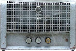
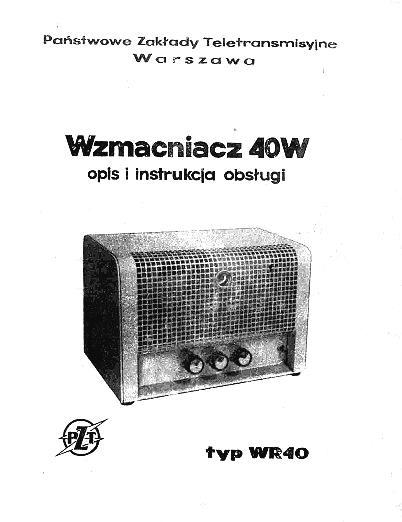
A tube amplifier mass-produced since the second half of the 50's of the 20th century. Manufactured by the State Teletransmission Company in Warsaw. WR40 "Ampli 40" tube amplifier was a portable device designed to create small broadcasting networks and to serve as audio amplifier for mass event organized in large rooms such as sports halls, school auditoriums, and events held in the open air.
Amplifier design
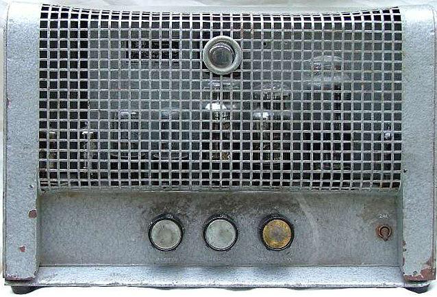
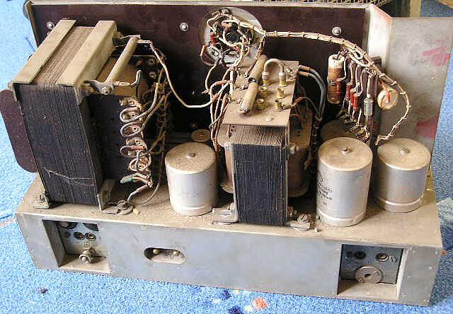
Amplifier is mounted inside a steel box painted with a gray "hammer" lacquer. The front panel is punched. WR40 chassis is rigid and stable. It has a form of welded cadmium-plated steel box.
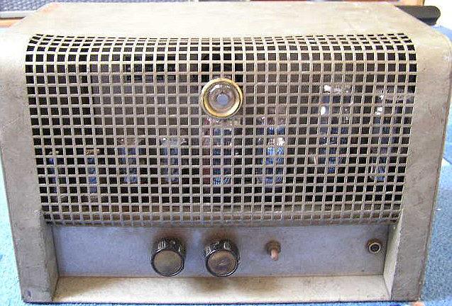
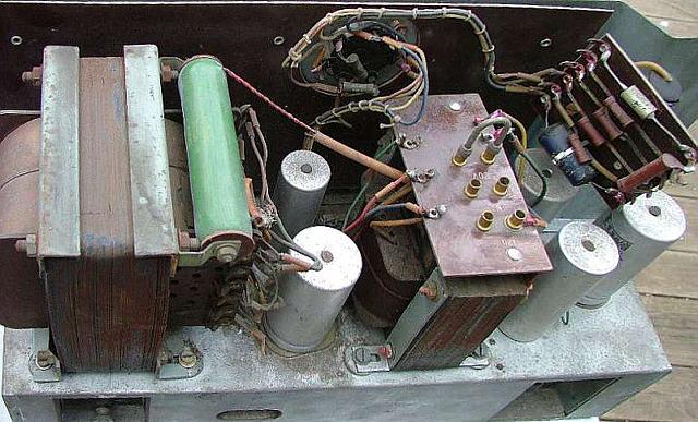
From the top, the chassis is divided by steel sheet. It separates (visible through the mesh of the case) hot electron tubes from the transformers and electrolytic capacitors.
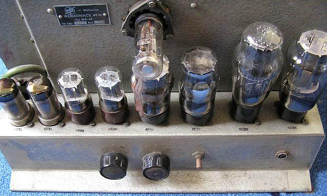
Preamplifier's tube sockets, phase inverter's tube socket, power supply electrolytic capacitors and inductive components: two transformers - output and mains are mounted on the chassis. The EM4 magic eye is screwed to the steel sheet separating the chassis.
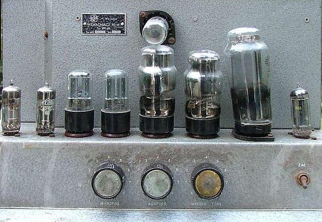
In front of the chassis there are: three potentiometers controlling the level of the input signal and tone, and power switch.
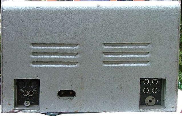
On the back of the chassis there is a "retro type" mains socket. The left "pocket" contains power and anode fuses, "banana" type speaker sockets and nut to attach the ground wire. In the right "pocket" there are two banana inputs ("Radio" and "turntable") and one coaxial microphone socket.
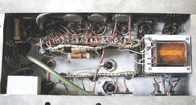
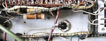
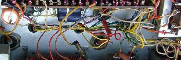
Inside the chassis there is a vertically placed plate riveted with bakelite terminal blocks with resistors and capacitors which are soldered and wired with tube sockets contacts. Wires are conducted in the form of bundles.
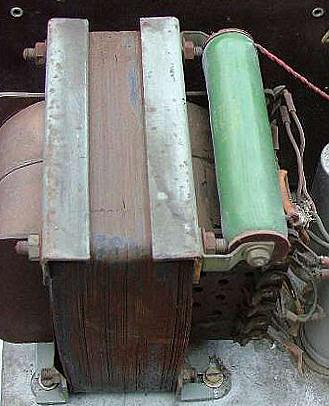
In the immediate vicinity of the rectifying tubes sockets the sizable power choke is located.
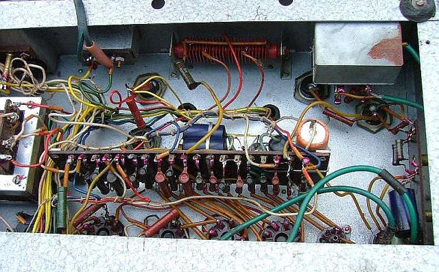
The output stage of the amplifier is a medium voltage class B push-pull circuit, very similar to the classic Williamson, realized by 6P3S beam tetrodes (6L6), loaded by the output transformer primary windings. Middle column cross-section of the core of the transformer is approximately 20cm2.
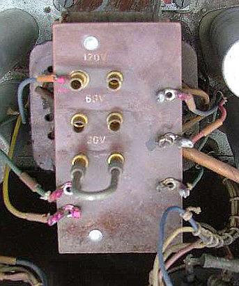
The bakelite plate placed on the transformer is equipped with three jumper switchable pairs of slots required to enable the output voltage setting of 30 (8ohms) - 60 - 120 V, depending on the load.
Power tubes grids are controlled by an expanded phase inverter system (6N8S tubes) providing a broad and uniform frequency response and low output internal resistance "seen" from the control grids of 6P3S tubes.
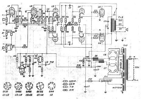
Power supply of the amplifier consists of two medium voltage sections, fed with the respective winding taps of common anode winding:
- supplying anode voltage of +420V for power tubes - rectifiers output is loaded with the "bleeder" (50K wire resistor),
- providing voltage of +350V for screen grids of power tubes, phase inverter, input stage and the "magic eye".
Negative voltage supplying power tubes grids (bias) and follower cathodes (L4) is taken from a separate winding connected to the selenium rectifier bridge. This voltage is set by the manufacturer and can not be adjusted.
Preliminary smoothing of the anode voltage is realized by the choke. It's two windings are connected in "antiparallel" directly to the cathodes of rectifier tubes. Such a system provides an exceptionally good ripple filtering, but the main justification for its use was the lack of electrolytic capacitors with large capacities and their high prices at the time. Anode and filament voltages are collected from a large power transformer.
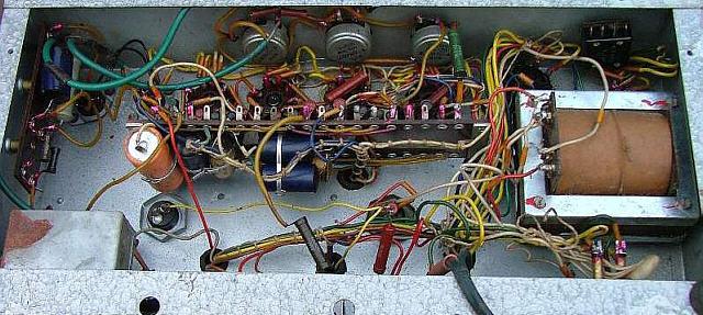
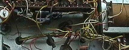
Connections inside the amplifier case are made of wires grouped in aesthetic bundles. The installation itself is a "point to point" type. However, the kind of curiosity is the fact that newer versions of this amplifier were assembled more and more messy!
The significant fault of amplifier design was using of a metal chassis to grounding purposes (as in ... the car) and the use of unbalanced (in addition one for all tubes) filament winding. The result is the formation of local "ground loops" and so annoying mains hum - amplifier buzzes even when twisted to a minimum gain.
Amplifier versions
"Ampli 40" amplifier was assembled in a number of slightly different design versions. Differences were associated with the anode power supply units and preamplifiers. The earliest versions used two (Polish production) 5C3S rectifying tubes (but I also met a copy of the amplifier with the 5C4S tube in the +350V section). The first modification was to replace one of them (branch +350 V) with EZ80 tube, the final change was the replacement of the remaining 5C3S tube by "european" AZ4 tube. Of course, this resulted in a change in filament voltage and so the filament winding in power transformer. (from 5V to 4V). Also preamplifier stage was modified: the original version based on loctal EF21 pentode was subsequently replaced by more modern noval EF80.
Technical specification
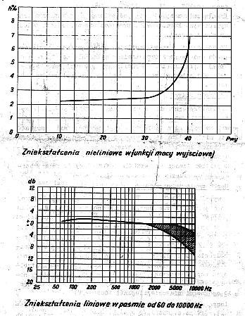
- outpu power: 40W (sinus),
- frequency range: 60Hz- 10kHz,
- total harmonic distortions: 7% (60Hz – 5kHz) / 40W,
- input sensitivity:
- „Radio/Turntable” = 0,25V/200k,
- „Microphone” = 0,06V/500k,
- input voltage for nominal output power: 1V,
- output voltages: 30V (for 8hms load), 60 and 120V.
Tubes
- EF21 - input preamplifiers , 2 pcs.,
- 6N8S - phase inverter and cathode follower, 2 pcs.,
- 6P3S - optput tubes, 2 pcs.,
- EM4 - level meter/ magic eye, 1 piece.,
- 5C3S - rectifier tubes, 2 pcs..
After modification:
- EF80 - input preamplifiers , 2 pcs.,
- EZ80 - rectifier tubei +350V,
- AZ4 - rectifier tubei +420V.
Remarks
WR40 broadcast Amplifier - "Ampli 40" - is the average quality acoustic amplifier with typical parameters required for reproduction of word-music programs.
Sturdy assembly using reliable components ensures this device extremely low failure rate and a remarkable stability of the parameters: the majority of common units of the device are still functional. These amplifiers still operate beeing equipped with the original tube sets - as clearly evidenced the excellent quality and longevity of vaccum tubes produced in Polan from that period.
But "there is no rose without a thorn": in spite of a relatively high anode voltage "Ampli 40" amplifier was not equipped with "stand by" circuir! As mentioned at the beginning of the description, the power supply used powerful hardwired-ceramic resistor/"bleeder" (R39, 10kΩ/50W - the original parts list has an error and gives 8W). Damage to the resistor resulted in a significant increase in the anode voltage above the allowable 450 V, which usually ended in a punch of electrolytic capacitor C1 (16uF/450/500V) and burning fuses in the transformer anode winding. Fuse protection was the most importand protection element of the amplifier. Mindless increase its value entailed the destruction of the rectifier tubes and sometimes the burning of the power transformer. In the modified Ampli 40 WR40/62 this drawback was eliminated.
Subjectively the sound of the amplifier can be described as undistorted and clean, warm and very dynamic - but with clearly audible hum.
The instrumental applications (electric guitar: solo and bass and organ) Ampli 40 was doing a surprisingly good! The sound was powerful and clear, but - like most contemporary "universal" amplifiers - not fit for the "distorted" sounds! In the end it was a broadcast not instrumental.
Remarks
- Amplifier photos come from an online auctions. I put them as anonymous: questions to exhibitors for permission to publish them remained unanswered!
- "Ampli 40" amplifier is not eligible for conversion or modification. The method of installation makes it virtually impossible. Even the limited introduction of modifications to improve its performance (eg, hum noise elimination by filament balancing) - would require almost total dismantling of the device.The only solution would be to completely disassembly and then assembly electronic parts again - according to the rules applied for the construction of this type of amplifiers:
- maintaining the existing electronic system - the parameters of these amps are so good that it is worth to take such a job,
- expanding the input circuits and tone correction, in order to give it the characteristics of a classic guitar amp (jazz, classic rock and blues), or microphone amp.
But perhaps the most reasonable is to leave this (now unique) amplifier in its original state: as a specific example of Polish technical thought, effectively reduced by existing technological barriers of the time.
Additional Resources
Instruction manual: part.1, part.2, part.3, part.4, part.5, part.6, part.7.
[last updated 9.04.2005]
(Written by Andrzej Żółtowski „ZoltAn”, Gliwice,